
How ideCAD defines structural systems for two earthquake directions according to ASCE 7-16?
-
The ductility levels of the structural systems in perpendicular directions cannot be chosen differently. They must be the same. It is controlled automatically.
-
Different responce modification coeffricients, R can be used in perpendicular directions.
-
The values for R, Ω0, and Cd at structural systems in Table 12.2-1 are chosen for structural steel and reinforced concrete systems by the user.
SYMBOLS
R = Response modification coefficient
hn = Structural height
12.2.2 Combinations of Framing Systems in Different Directions
It is allowed to use different seismic-force resisting systems to resist seismic forces along the two orthogonal axes of the structure. Where different systems are used, the R, Cd, and Ω0 coefficients apply to each system, including the structural system limitations contained in Table 12.2-1.
Depending on the structural systems selected, one of the two systems may limit the extent of the overall system with regard to structural system limitations or structural height, hn.
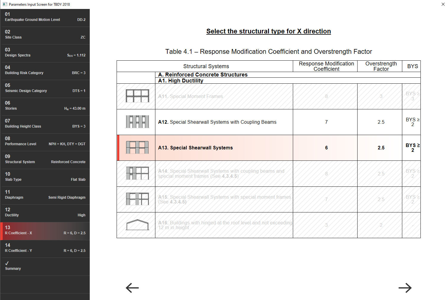
With the ASCE 7-16 Wizard, the ductility levels of the structural systems in perpendicular directions are selected the same. Different seismic force-resisting systems can be used along each of the two orthogonal axes of the structure. As can be seen in the picture below, there are structural system options with special frame systems in Table 12.2-1 on the R coefficient selection screen of a structure with special frame systems.
|
Structural System Type |
Response Modification Coefficient, R |
Overstrengh Factor, Ωo |
Deflection Amplification Factor, Cd |
Structural System Limitations Including Structural Height, hn (ft) Limits |
||||
|---|---|---|---|---|---|---|---|---|
|
Seismic Design Category |
||||||||
|
B |
C |
D |
E |
F |
||||
|
A. Bearing Wall Systems |
||||||||
|
A1 - Special reinforced concrete shear walls |
5 |
21/2 |
5 |
NL |
NL |
160 |
160 |
100 |
|
A2 - Ordinary reinforced concrete shear walls |
4 |
21/2 |
4 |
NL |
NL |
NP |
NP |
NP |
|
A3 - Detailed plain concrete shear walls |
2 |
21/2 |
2 |
NL |
NP |
NP |
NP |
NP |
|
A4 - Ordinary plain concrete shear walls |
11/2 |
21/2 |
11/2 |
NL |
NP |
NP |
NP |
NP |
|
B. Building Frame Systems |
||||||||
|
B1 - Steel eccentrically braced frames |
8 |
2 |
4 |
NL |
NL |
160 |
160 |
100 |
|
B2 - Steel special concentrically braced frames |
6 |
2 |
5 |
NL |
NL |
160 |
160 |
100 |
|
B3 - Steel ordinary concentrically braced frames |
31/4 |
2 |
31/4 |
NL |
NL |
35 |
35 |
NP |
|
B4 - Special reinforced concrete shear walls |
6 |
21/2 |
5 |
NL |
NL |
160 |
160 |
100 |
|
B5 - Ordinary reinforced concrete shear walls |
5 |
21/2 |
41/2 |
NL |
NL |
NP |
NP |
NP |
|
B6 - Detailed plain concrete shear walls |
2 |
21/2 |
2 |
NL |
NP |
NP |
NP |
NP |
|
B7 - Ordinary plain concrete shear walls |
11/2 |
21/2 |
11/2 |
NL |
NP |
NP |
NP |
NP |
|
C. Moment-Resisting Frame Systems |
||||||||
|
C1 - Steel special moment frames |
8 |
3 |
51/2 |
NL |
NL |
NL |
NL |
NL |
|
C2 - Steel special truss moment frames |
7 |
3 |
51/2 |
NL |
NL |
160 |
100 |
NP |
|
C3 - Steel intermediate moment frames |
41/2 |
3 |
4 |
NL |
NL |
35 |
NP |
NP |
|
C4 - Steel ordinary moment frames |
31/2 |
3 |
3 |
NL |
NL |
NP |
NP |
NP |
|
C5 - Special reinforced concrete moment frames |
8 |
3 |
51/2 |
NL |
NL |
NL |
NL |
NL |
|
C6 - Intermediate reinforced concrete moment frames |
5 |
3 |
41/2 |
NL |
NL |
NP |
NP |
NP |
|
C7 - Ordinary reinforced concrete moment frames |
3 |
3 |
21/2 |
NL |
NP |
NP |
NP |
NP |
|
D. Dual Systems with Special Moment Frames Capable of Resisting at Least 25% of Prescribed Seismic Foces |
||||||||
|
D1 - Steel eccentrically braced frames |
8 |
21/2 |
4 |
NL |
NL |
NL |
NL |
NL |
|
D2 - Steel special concentrically braced frames |
7 |
21/2 |
51/2 |
NL |
NL |
NL |
NL |
NL |
|
D3 - Special reinforced concrete shear walls |
7 |
21/2 |
51/2 |
NL |
NL |
NL |
NL |
NL |
|
D4 - Ordinary reinforced concrete shear walls |
6 |
21/2 |
5 |
NL |
NL |
NP |
NP |
NP |
|
E. Dual Systems with Intermediate Moment Frames Capable of Resisting at Least 25% of Prescribed Seismic Foces |
||||||||
|
E1 - Steel special concentrically braced frames |
6 |
21/2 |
5 |
NL |
NL |
35 |
NP |
NP |
|
E2 - Special reinforced concrete shear walls |
61/2 |
21/2 |
5 |
NL |
NL |
160 |
100 |
100 |
|
E8 - Ordinary reinforced concrete shear walls |
51/2 |
21/2 |
41/2 |
NL |
NL |
NP |
NP |
NP |
|
F. Shear Wall-Frame Interactive System with Ordinary Reinforced Concrete Moment Frames And Ordinary Reinforced Concrete Shear Walls |
||||||||
|
F1 - Shear wall-frame interactive system |
41/2 |
21/2 |
4 |
NL |
NP |
NP |
NP |
NP |
|
G. Cantilevered Column Systems Detailed to Conform to the Requirement for |
||||||||
|
G1 - Steel special cantilever column systems |
21/2 |
11/4 |
21/2 |
35 |
35 |
35 |
35 |
35 |
|
G2 - Steel ordinary cantilever column systems |
11/4 |
11/4 |
11/4 |
35 |
35 |
NP |
NP |
NP |
|
G3 - Special reinforced concrete moment frames |
21/2 |
11/4 |
21/2 |
35 |
35 |
35 |
35 |
35 |
|
G4 - Intermediate reinforced concrete moment frames |
11/2 |
11/4 |
11/2 |
35 |
35 |
NP |
NP |
NP |
|
G5 - Ordinary reinforced concrete moment frames |
1 |
11/4 |
1 |
35 |
NP |
NP |
NP |
NP |
|
H. Steel Systems not Specifically Detailed for Seismic Resistance, Excluding Cantilever Column Systems |
||||||||
|
H - Steel Systems not Specifically Detailed for Seismic Resistance |
3 |
3 |
3 |
NL |
NL |
NP |
NP |
NP |