
-
The in-plane average tensile, pressure and shear stresses occurring under the effects of earthquakes, which are increased with the vertical loads and the Resistance Excess Coefficient D, are automatically controlled.
-
In-plane tensile, compression and shear stresses are automatically found in slabs using shell finite elements.
ICONS
D = Strength Excess Coefficient
f cd = Design compressive strength of concrete
f ctd = Design tensile strength of concrete
f yd = Design yield strength of reinforcement
f ck = Characteristic cylinder compressive strength of concrete
ρ = ratio of reinforcement remaining from the required for flexural strength
τ r = In- plane shear stress strength
In-Plane Axial and Shear Stresses in Slabs
Floor elements are modeled with shell finite elements. When the solution is made with the acceptance of the elastic diaphragm (semi-rigid diaphragm), in-plane and out-of-plane stresses occur in floors. All in-plane and out-of-plane stresses in slab finite elements are calculated for each loading combination.
In the design, it must be shown that in-plane stresses caused by horizontal loads on the slab are met. Additional stresses occur in areas where horizontal earthquake forces are directly transferred from the floor to vertical elements such as columns and curtains. If the floors are connected to these elements by beams, the additional stresses are not present at significant levels, as the stresses are transmitted along the edges of the beams. However, if the floors are supported directly to columns and curtains without beams, significant stress concentrations may occur in the joints. Also, the presence of gaps in these areas causes additional stress increases. These areas of the floors should be examined in detail and these stresses should be met. In reinforced concrete structures, additional reinforcement may be required for force transmission between slab and vertical bearers such as columns and curtains. If there is no large gap in the beamed slab floors, these forces are transferred without causing significant effects on the floor. Floor discontinuities and gaps can cause stress concentrations during the transmission of earthquake loads to vertical bearing elements, as well as prevent the floor from acting like a rigid diaphragm in its own plane.
In Article 7.11.3 of TBDY, it is stated that in-plane axial pressure, axial tensile and in-plane shear stresses in the floors of buildings with and without beams will be made by the acceptance of elastic diaphragm. From the results of crustal finite elements in slabs, in-plane axial pressure, axial tensile and shear stresses are calculated in all loading combinations under the combined effect of earthquake loads calculated by taking into account the vertical loads multiplied by the load coefficients and the Strength Excess Coefficient D.
By using the excessive strength coefficient, in case the earthquake exceeds the predicted value, the expected capacity increase in other elements is also created in the floor, ensuring that the weak ring is not flooring.
Pressure Stress Control
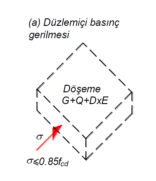
According to Article 7.11.3 of TBDY , the compressive stress calculated under the combined effect of earthquake loads calculated by taking into account the vertical loads and the Strength Excess Coefficient D should not exceed 0.85f cd in order to prevent pressure crush within the floor plane . f cd is the design compressive strength of concrete. The following picture shows which plane the in-plane compressive stress is in for a single direction in a representative shell finite element. These stresses are calculated on all surfaces of the finite element.
With the semi-rigid diaphragm solution, the in-plane compressive stresses in floors are obtained from the F11 and F22 results calculated under the combined effect of the earthquake loads calculated by taking into account the vertical loads multiplied by the load coefficients and the Strength Excess Coefficient D.
F11 and F22 are the forces that are parallel to the floor plane and perpendicular to the slab edges that are formed in the direction of 1 and 2, respectively, according to the local axes of the elements (floor and curtain) modeled with shell finite elements. If these forces are negative (-), this force is the pressure force. When these values (F11 and F22) are divided by the slab thickness, the in-plane pressure stresses occurring in the slab are found.
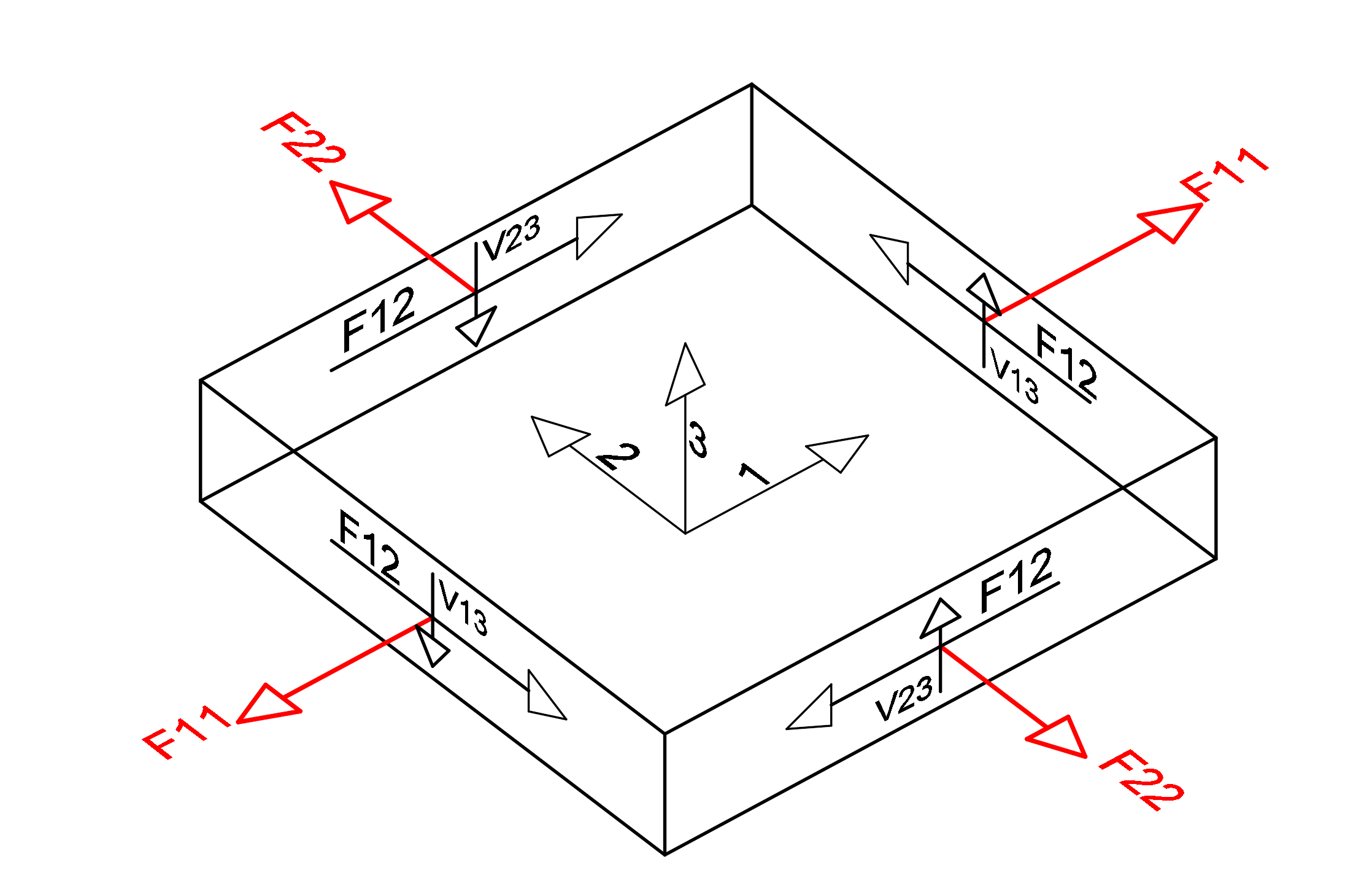
The picture above shows the local axes of a finite element and a free body diagram. The unit length forces in the finite element in the middle of this finite element with respect to the local axis directions indicated by 1,2,3 are shown. F11 and F22 values are shown in red. In the compressive stress control, the F11 and F22 values calculated according to the local axis of the element are divided by the slab thickness and the compressive stress value formed in the finite element is found.
In all of the finite elements in slabs, the above procedures are performed for all loading combinations. As a result of this analysis, the highest stress value is compared with 0.85f cd value and conformity is checked.
Tensile Stress Control
According to Article 7.11.3 of TBDY , it is assumed that if the tensile stress value calculated under the combined effect of earthquake loads calculated by taking into account the vertical loads and the Extra Strength Coefficient D is greater than the design tensile strength, f ctd , of the concrete , cracking occurs and the tensile stress is only met by the reinforcement. is. In this case, in order to meet the in-plane tensile stress, the remaining reinforcement that is required for the flexural strength of the slab can be used and additional reinforcement can be placed when necessary. Tensile stress value, ρf ydSecurity control is made by comparing it with its value. Here ρ is the ratio of the reinforcement not required for bending and added as needed to the slab cross section. If the tensile stress value calculated under the combined effect of the earthquake loads calculated considering the vertical loads and the Strength Excess Coefficient D is less than f ctd , then reinforcement calculation is not required. In this case, it is accepted that the slab concrete is not cracked and the tensile stress is borne by the concrete.
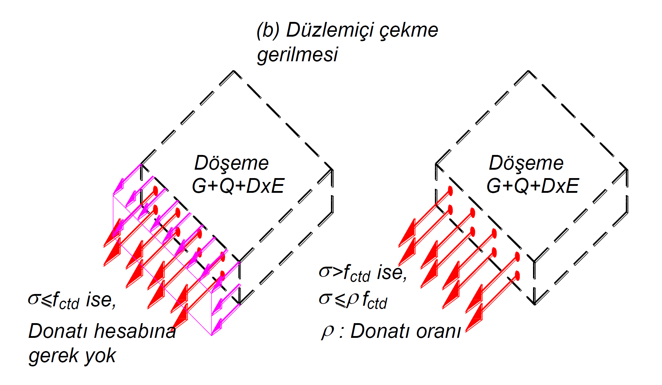
The following picture shows which plane the in-plane tensile stress is in for a single direction in a representative shell finite element. In the picture on the left, the tensile stress value calculated under the combined effect of the earthquake loads calculated considering the vertical loads and the Strength Excess Coefficient D is less than f ctd . For this reason, no extra reinforcement control is made for this control except for the flexural reinforcement of the slab. Because concrete can meet the desired tensile stress. However, in the picture to the right, the tensile stress value calculated under the combined effect of earthquake loads calculated by taking into account the vertical loads and the Strength Excess Coefficient D, f ctdis greater than. For this reason, tensile stress is calculated with the remaining reinforcement from the reinforcement required for flexural strength.
With the semi-rigid diaphragm solution, the in-plane tensile stresses in floors are obtained from the F11 and F22 results calculated under the combined effect of the earthquake loads calculated by taking into account the vertical loads multiplied by the load coefficients and the Strength Excess Coefficient D.
F11 and F22 are forces that are parallel to the floor plane and perpendicular to the slab finite element edges that are formed in 1 and 2 directions, respectively, according to the local axes of the elements (floor and curtain) modeled with shell finite elements. If these forces are positive (+), this force is the pulling force. When these values (F11 and F22) are divided by the slab thickness, the in-plane tensile stresses occurring in the slab are found.
The picture above shows the local axes of a finite element and a free body diagram. The unit length forces in the finite element in the middle of this finite element with respect to the local axis directions indicated by 1,2,3 are shown. F11 and F22 values are shown in red. In the tensile stress control, the F11 and F22 values calculated according to the local axis of the element are divided by the slab thickness and the tensile stress value formed in the finite element is found.
In all of the finite elements in slabs, the above procedures are performed for all loading combinations. According to Article 7.11.3 of TBDY , at the end of this analysis, the greatest tensile tensile stress is compared with f ctd . If the stress is less than f ctd , sufficiency is achieved. If the tensile stress occurring in the slab plane is greater than the design tensile stress f ctd of the concrete , the yield strength of the remaining reinforcement required for the flexural strength of the slab should not exceed ρf yd . The ratio of the remaining reinforcement ρ that is required for the bending strength and the design yield stress of the slab reinforcement f ydThe yield strength of the remaining reinforcement required for the flexural strength of the slab is equal to the product of ρf yd .
Since the design tensile strength f ctd of concrete is very small compared to the design compressive strength f cd of the concrete , the slab tensile stress is mostly borne by the slab reinforcement. For this reason, local floors should be defined in areas where tensile stress is high, and appropriate reinforcements should be placed in a way that takes into account the slab calculation axes.
Shear Stress Control
The in-plane shear stresses in floors with the semi-rigid diaphragm solution are the stresses calculated under the combined effect of the earthquake loads calculated by taking into account the vertical loads multiplied by the load coefficients and the Strength Excess Coefficient D. The upper limit of the horizontal shear stresses in both directions within the slab plane in Equation 7.25 according to Article 7.11.3 of TBDY ,
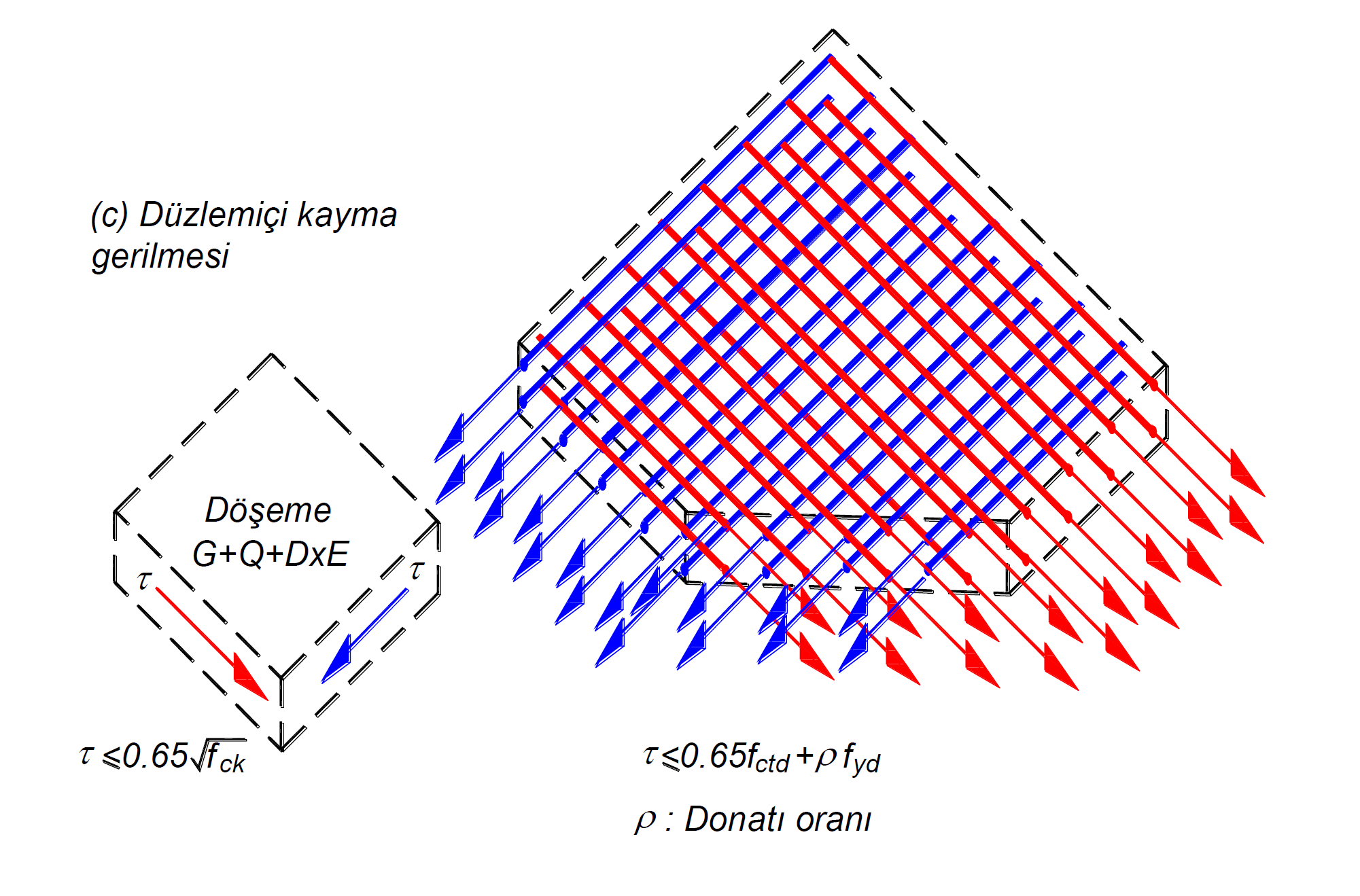
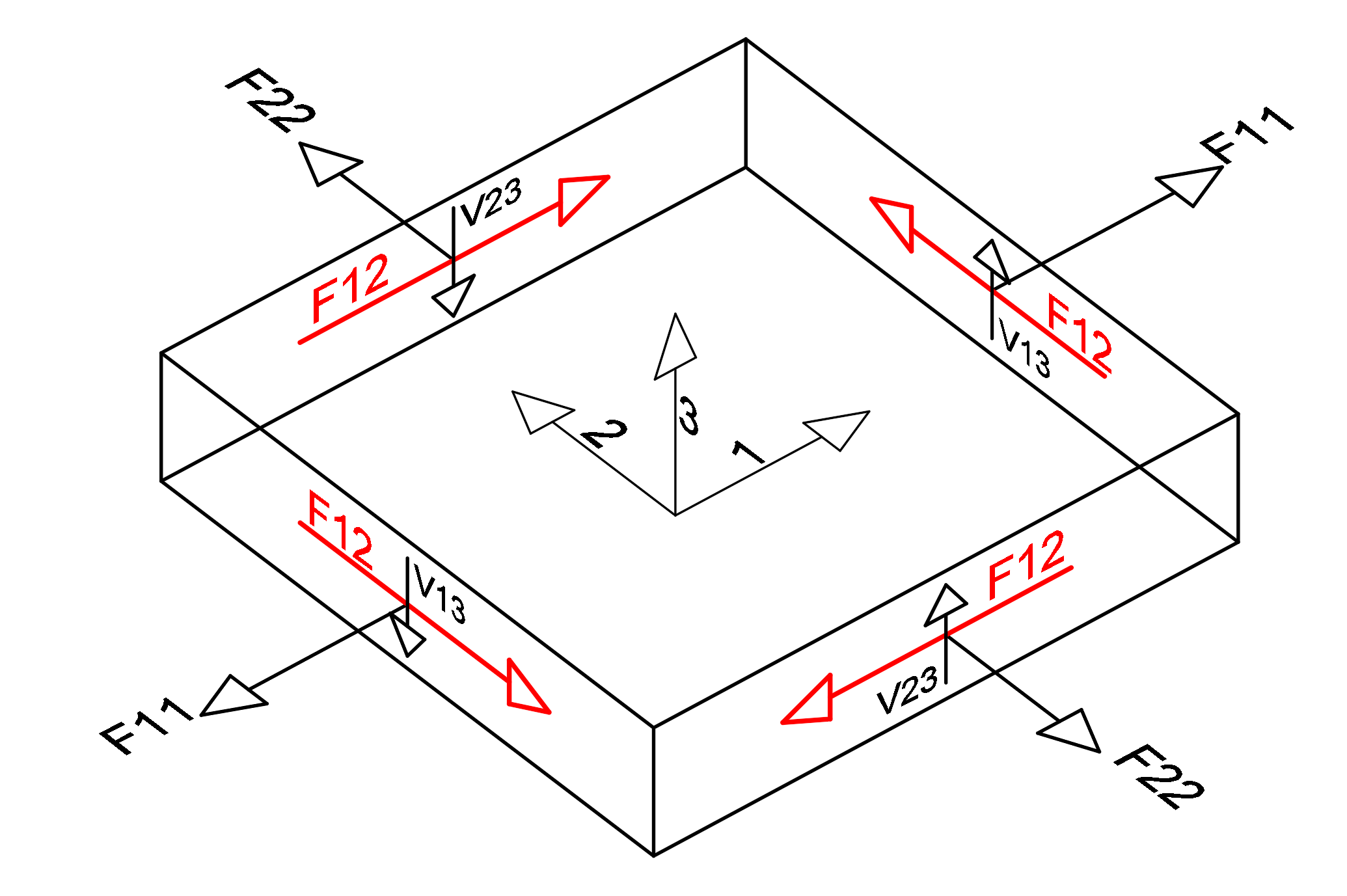
given as. In this equation, f ctd means the design tensile strength of concrete and f yd means the design yield stress of the slab reinforcement. Also, ρ is the ratio of the reinforcement not required for bending to the slab cross section parallel to the shear stress. In this way, it is aimed to meet the oblique tensile stresses caused by shear stresses with reinforcement. The situation of this reinforcement can be compared to the stirrup parallel to the shear force in the beam sections or to the horizontal body reinforcement meeting the shear force in the curtain. The upper limit of the in-plane shear stresses is 0.65 (f ck ) 1/2 to prevent crushing of concreteits value has been stipulated. In the picture below, the in-plane shear stresses calculated under the common t of the earthquake loads calculated taking into account the vertical loads and the Strength Redundancy Coefficient D are shown in a representative finite element. Red arrows indicate that the shear stress shown with the red arrow will be met by the reinforcements parallel to this stress direction. A similar situation is valid for blue stretch.
TBDY Article 7.11.3 according ρ bending residual than required for recovery and parallel to the shear stresses
that will be placed in the direction slab reinforcement ratio, f yd design yield stress of slab reinforcement and f ctd concrete design tensile strength, including horizontal shear stress in the plane of laying TBDY It shall not exceed the limit value given by Equation 7.25 .
If the in-plane shear stress exceeds 0.65 (f ck ) 1/2 ', the slab concrete is considered to be crushed. Therefore, any reinforcement placement will not be sufficient to bear this stress.
With the semi-rigid diaphragm solution, the in-plane shear stresses in floors are obtained from the F12 results calculated under the combined effect of the earthquake loads calculated by considering the vertical loads multiplied by the load coefficients and the Strength Excess Coefficient D.
F12 is the shear force of the shell finite element calculated in the plane and occurring in unit length. This value has equal value on all surfaces of the shell finite element and is shown in red in the picture below. The in-plane shear stress value is obtained by dividing the F12 value by the slab thickness.
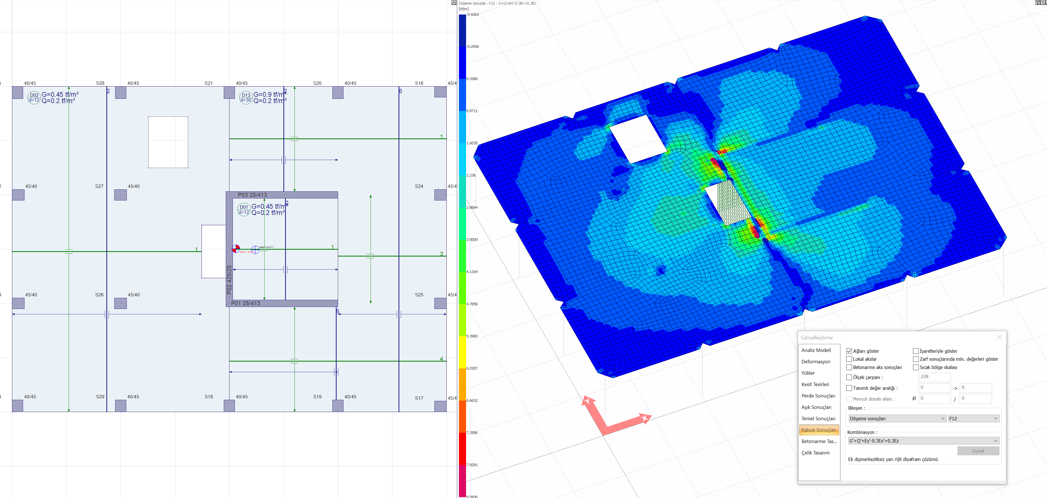
In buildings with A2 and A3 type irregularities, according to Article 3.6.2.2 of TBDY , floor floors are modeled with shell finite elements to show that they can safely transfer earthquake forces between vertical bearing system elements in their own planes. A2 and A3 type irregularities create discontinuities in the floors and these discontinuities cause the slab stresses to grow at certain points. The following picture shows the gaps in the plan plane and the variation of the slab in-plane shear stresses. As can be noticed in the picture, stress concentrations occur at the points where the floor gaps are located.
Next Topic