
Symbols
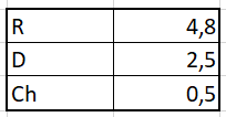
D = Strength excess coefficient
R = Carrier system behavior coefficient
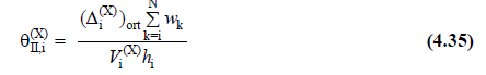
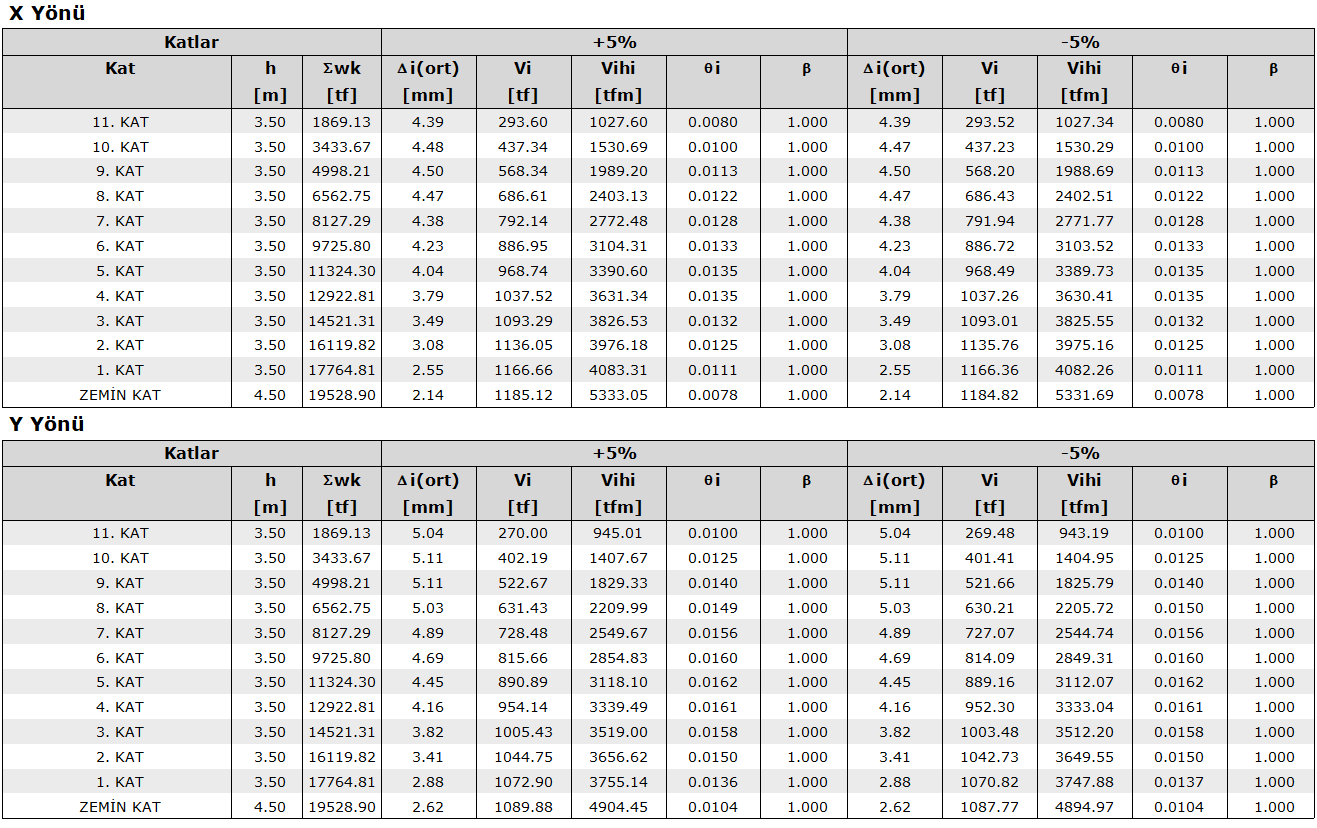
θII,i(X) = (X) second order indication value defined for each i'th floor in the earthquake direction
θII, max (X) = (X) defined in the earthquake direction maximum second order indication value
Vi (X) = (X) reduced floor shear force at the i'th storey in the earthquake direction [kN]
hi = height of the i'th storey [m]
∆i,avg (X) = (X) Average reduced relative storey drift expressing the displacement difference between two consecutive floors in the earthquake direction [m]
wk = total weight acting on the kth floor [kN]
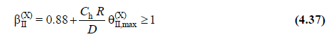
βII(X) = Second order amplification coefficient
βtE(X) = Equivalent base shear force magnification coefficient
-
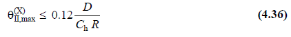
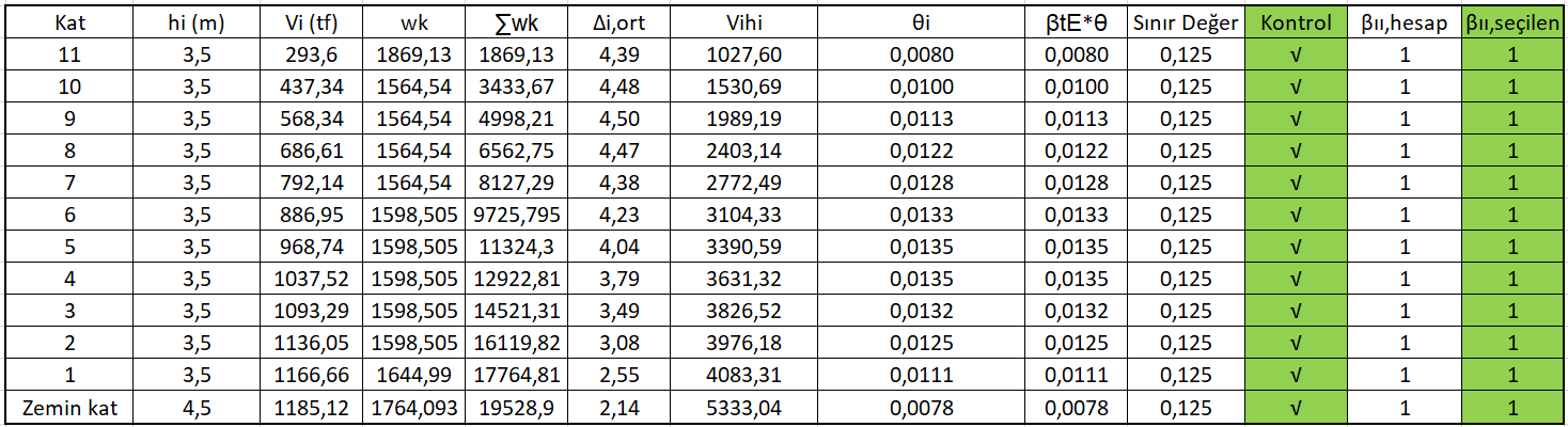
For each direction, second order indicator value θ II, i is calculated according to TBDY 4.9.2 for all floors . If maximum θ II, max satisfies the following condition; Second order effects are not taken into account in determining the internal forces based on design.
-
C h is a coefficient calculated based on the nonlinear hysteretic behavior of the structural system and 0.5 is taken for reinforced concrete as per TBDY 2018 4.9.2.2.
-
If the condition given in Equation 4.36 is not fulfilled , only the internal forces obtained from the horizontal earthquake effects are increased with the II coefficient determined by the following equation .
-
This value, calculated for all floors, is used only to increase the internal forces of the upper section elements in accordance with TBDY 4.9.2.4.
-
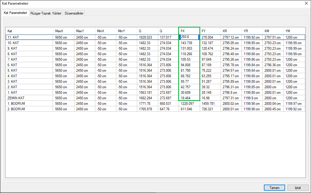
For manual calculation, V i and w k values are obtained from the Floor Parameters section on the upper toolbar Analysis and Design tab in the program .
-
From the above table, X direction for the floor forces, Vi, FX; For Y direction floor forces, FY columns are used. Since the values in the FX column are only the force acting on the relevant floor, the total shear force diagram is created for the building by summing it down. The values given in column Vi in the table below were obtained in this way.
-
For wk, the total weight acting on the floor, the values in columns G and Q from the table above are combined as G + 0.3Q. Here 0.3 is the live load participation coefficient and 0.3 is chosen for this building.
-
Average floor displacement values were used directly as values in the program report. Equation 4.36 is used for the limit value calculation. The values of the building used in the calculation are as follows:
-
βtE(X) = 1,determined in the Increasing of Increasing Reduced Internal Forces and Displacements According to Equivalent Base Shear Force it is included in the calculation asβtE= 1 in thetable above.
-
The result of the calculation made for the building is given in the earthquake regulation report.
-
It is determined as β II = 1 for the building . There is no question of any increase. If it is greater than 1, it must be increased according to the regulation or the engineer may choose to increase the stiffness until II = 1.
-
The excel table for the manual part of the account can be obtained here.