
Symbols
Ag : Gross cross-sectional area of member
Ae : Effective area
c1, c2 : Effective width imperfection adjustment factor determined from Table 8.2
Fcr : Critical stress
Fe : Elastic buckling stress
Fe1 : Elastic buckling stress determined according to Equation 8.25,
Fy : Specified minimum yield stress of the type of steel being used,
K : Effective length factor
L: Laterally unbraced length of the member
Lc : Effective length of the member, (= KL)
i: Radius of gyration
λ: Width-to-thickness ratio for the element
λr : Limiting the width-to-thickness ratio as defined in Table 5.1a
Lcz : Effective length of member around the z-axis (= KL)
Ix , Iy : Moment of inertia about the principal axes, in.4 (mm4)
J: Torsional constant, in.4 (mm4)
Cw : Warping constant, in.6 (mm6)
E: Modulus of Elasticity of Steel
Fy : Specified minimum yield stress of the type of steel being used
Fey : Elastic buckling stress in buckling limit state with bending around the y-axis
Fez : Elastic buckling stress in torsional buckling limit state z-axis
G: Shear modulus of elasticity of steel = 11,200 ksi (77 200 MPa)
H: Flexural constant
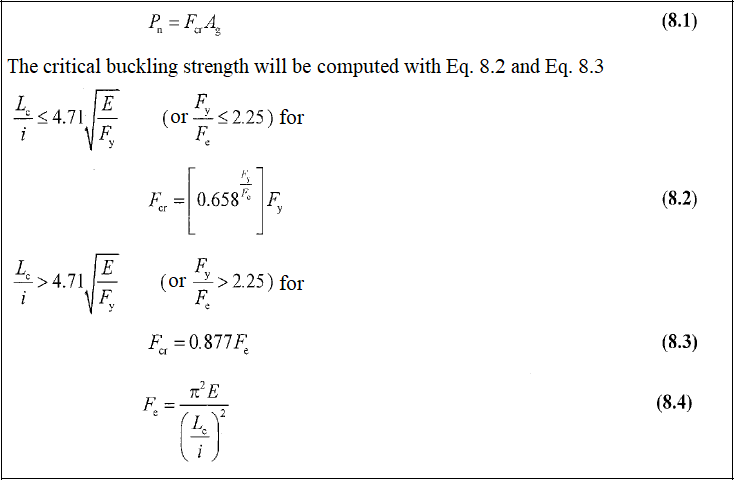
Flexural Buckling Limit State
-
The limit state of flexural buckling is applicable for axially loaded columns with, doubly symmetric sections such as bars, HSS and round HSS, and I-shapes and single symmetric sections, such as T- and U-shapes. Flexural buckling is the simplest type of buckling.
Design with ÇYTHYE 2018
-
The compressive strength of the elements is determined according to the axial force acting into the center of gravity section. According to the regulation, the bending buckling limit state is taken into account in all compression elements, regardless of cross-section properties. The equations used for this are given below in order.
-
First of all, local buckling control should be done. The calculation is made according to whether the elements are compact or non-compact.
Compressive Strength in Non-Slender Elements
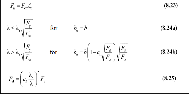
Compressive Strength in Slender Elements
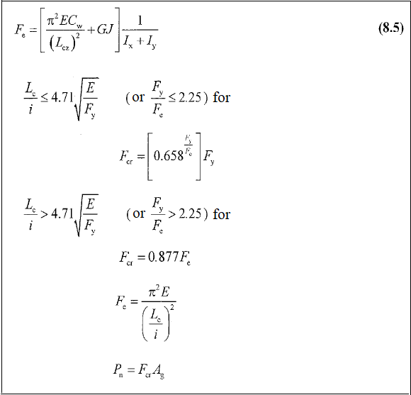
Torsional Buckling Limit State
-
Buckling occurs when the element rotates around its longitudinal axis. It occurs in positive (+) shaped built-up elements or channel cross-section that are compressive elements consisting of 4 equal leg angle placed back to back.
Design with ÇYTHYE 2018
-
The compressive strength of the elements is determined according to the axial force acting into the center of gravity section.
-
The torsional buckling limit state occurs when the element rotates around its longitudinal axis (positive (+) shaped built-up elements or channel cross-section that are compressive elements consisting of 4 equal leg angle placed back to back) and the elastic buckling stress Fe is calculated by equation 8.5.
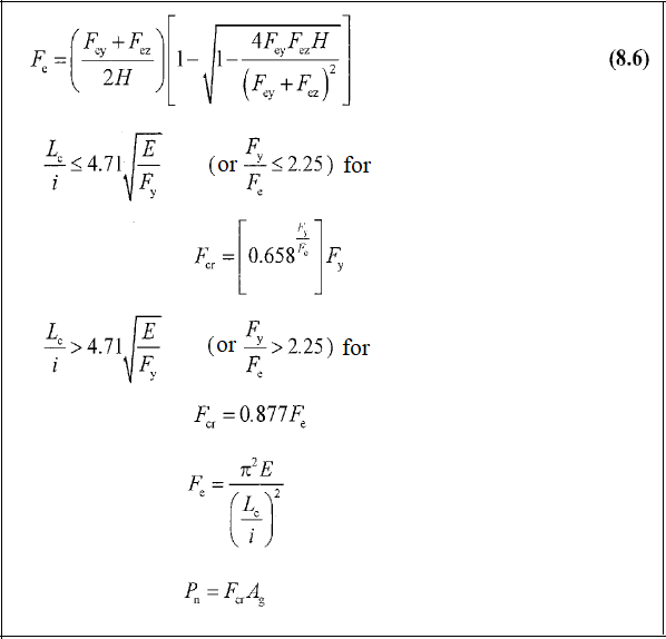
Flexural-Torsional Buckling Limit State
-
When symmetry axis is the y-axis, where the buckling around the y-axis is caused by the bending and rotation of the element around its longitudinal axis on the Double-Leg angle, T profile, U profile and Single Equal-Leg angle sections that are under compression around their symmetry axes.
Design with ÇYTHYE 2018
-
The compressive strength of the elements is determined according to the axial force acting into the center of gravity section.
-
With the symmetry axis being the y-axis, the elastic buckling stress Fe in the flexural-torsional buckling limit state where buckling around the y-axis occurs by bending and rotating around the longitudinal axis, Fe is calculated according to equation 8.6.
Next Topic