
Concrete design results of stairs and inadequacies regarding stairs are displayed in the Stair Reinforcements dialog. Straight and additional reinforcement results are given in the Stair Reinforcements dialog.
Location of the Stair Reinforcements Dialog
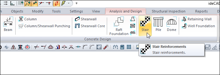
After the analysis, you can access it by clicking the Stair Reinforcement command under the Concrete Design title of the ribbon menu Analysis and Design tab .
Stair Calculations Tab
|
Specifications |
|---|
|
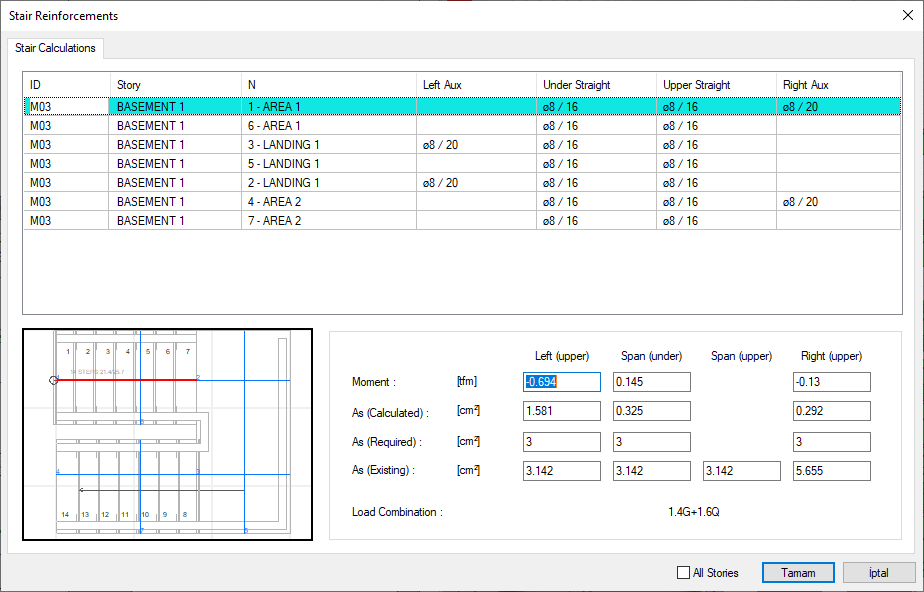
ID 
It is the display name of the stair. |
|
Story 
It is the name of the story where the stair is located. |
|
N 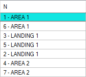
It is the number of account axes defined in the relevant regions, including curved arm and landing areas on the stair. |
|
Left aux 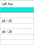
It is the diameter and the spacing in cm of the additional rebar calculated on the left support section on the relevant calculation axis. The diameter and range of the rebar can be changed by double clicking on it. |
|
Under straight 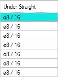
It is the diameter and interval in cm of the rebar under the section on the axis of the relevant calculation. The diameter and range of the rebar can be changed by double clicking on it. |
|
Upper straight 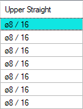
It is the diameter and interval in cm of the rebar on the section on the axis of the relevant calculation. The diameter and range of the rebar can be changed by double clicking on it. |
|
Right aux 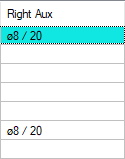
It is the diameter and the spacing in cm of the additional rebar calculated on the right support section on the relevant calculation axis. The diameter and range of the rebar can be changed by double clicking on it. |
|
Schematic drawing of stair 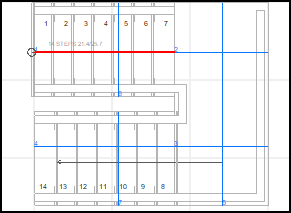
|
|
Left (upper) 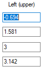
Defines the upper part of the section belonging to the left support of the slab for the investigated concrete calculation axis. |
|
Span (under) 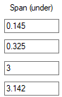
It defines the lower part of the section in the slab opening in the analyzed concrete calculation axis. |
|
Span (upper) 
Defines the upper part of the section in the slab opening in the analyzed concrete calculation axis. |
|
Right (upper) 
It defines the upper part of the section belonging to the right support of the slab in the analyzed concrete calculation axis. |
|
Load combination Design is the name of the combination in which the moment is found. |
|
All Stories It lists the stories on the screen throughout the entire story. |
|
Ok It saves the changes made and closes the dialog. |
|
Cancel Closes the dialog without saving the changes made. |
|
Using the Shift key In this tab, you can select more than one row with the Shift key, enter a value by double-clicking any cell whose value is open to change, and make that value apply to all selected rows. |
|
Using the Ctrl key Ctrl key, on the other hand, selects the lines in between one by one. |
Next Topic
Related Topics