-
In buildings where reinforced concrete walls with or without high ductility bond beams are used together with frames of high ductility level, the sum of the overturning moments caused by earthquake loads at the base of the walls is automatically controlled by the total tipping moment of the building according to Equation 4.2 .
ICONS
BYS = Building Height Class
DTS = Earthquake Design Class
D = Strength Redundancy Coefficient
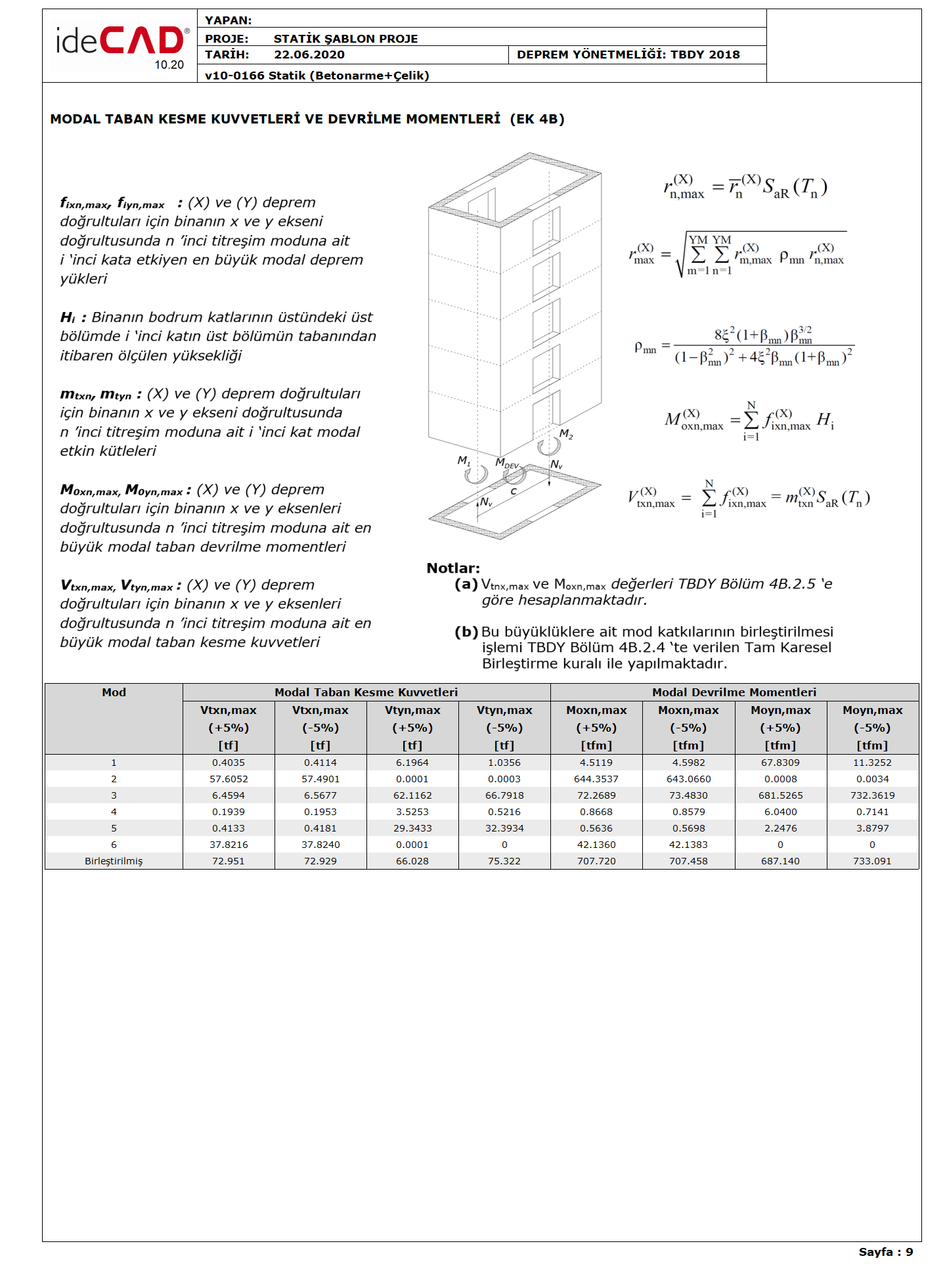
M DEV = Tipping moment caused by earthquake loads at the base of the reinforced concrete wall or braced frame
M o = Total tipping moment at the base from earthquake loads for the whole building
R = Structural System Behavior Coefficient
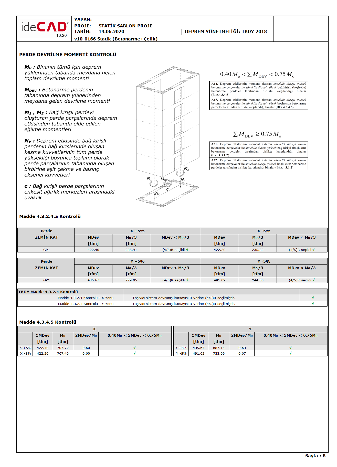
In buildings where high ductility bond beams (with or without gaps) cast-in-place reinforced concrete walls and frames with high ductility transferring moment are used together, the sum of the tipping moments at the base of the curtains due to earthquake loads, M DEV , is the total tipping moment caused by earthquake loads for the whole building, M o shall not be less than 40% and more than 75%. Equation 4.2 shows this relation.

Equation 4.2 shows the sum of the overturning moments caused by the earthquake loads at the base of the walls as M DEV , and the total overturning moment at the base due to the earthquake loads for the whole building, M o .
If the condition that the upper limit does not meet in Equation 4.2 occurs, ∑M DEV > 0.75M o The R and D coefficients defined in Table 4.1 for the cases where all earthquake effects are met with walls with high ductility level and the maximum permissible DMS will be taken into consideration.
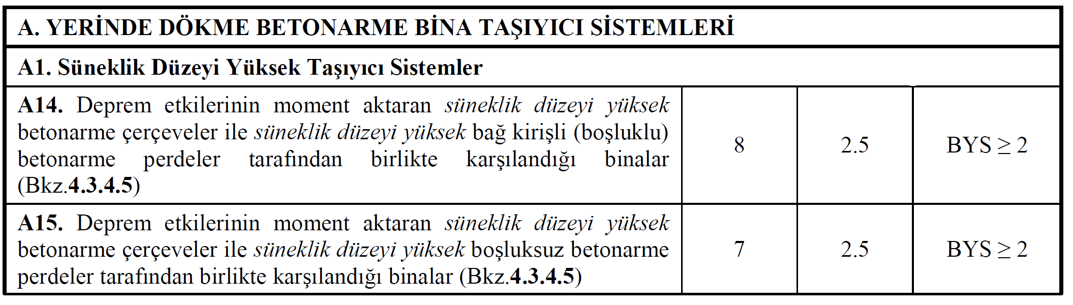
Said building under normal conditions of high ductility level bond beams (with spaces) or without cast in-situ reinforced concrete transfer torque with curtains that ductility level high as the carrier system is used together with the framework of the A14 and A15 carrier systems should be selected.
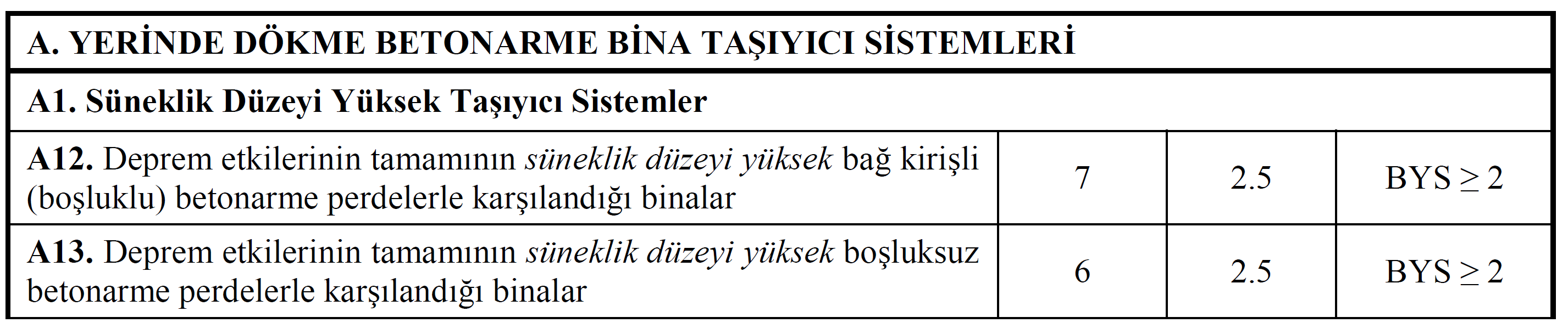
However, since Equation 4.2 upper boundary condition is not fulfilled [∑M DEV > 0.75M o ], it is assumed that all earthquake effects are met with walls with high ductility level with or without gaps. For this reason , A12 or A12 bearing systems should be chosen as the carrier system, even if there are frames that transfer moment in buildings where [∑M DEV > 0.75M o ] condition is not met . In this case, the carrier system behavior coefficient R value will decrease by one.
If there is a condition that the lower limit does not meet in Equation 4.2 , 0.40M o > ∑M DEV. The R and D coefficients given in Table 4.1 will not be changed, but one more of the allowed BYS will be considered. In this case , A14 and A15 carrier systems can be selected in Table 4.1 . However, in the case of [0.40M o > ∑M DEV ], the maximum allowed DMS value is 3, not 2.
The "Curtain Tipping Moment Control" report of a building where high ductility level frames are used together with high ductility level cast-in-place reinforced concrete walls are shown in the picture below. As it is seen in Equation 4.2 , the choice of carrier system was made as A14 and the allowed building height class was 2.
The sum of the overturning moments caused by earthquake loads at the base of the walls, M DEV , the total overturning moment occurring at the base from earthquake loads for the whole building, M o values are calculated by using the modal combination method described in Annex 4B.2.5 of TBDY . Below is a sample report where the modal base shear forces and the corresponding base overturning moment are calculated according to TBDY Annex 4B.2.5 .