
-
The earthquake force control, which is transferred from the floor to the curtain or the curtain arm in a strong direction, is done automatically in accordance with 7.11.5 .
-
The earthquake force to be transferred from the slab to the curtain or the curtain arm in a strong direction is calculated automatically as the difference of the shear forces DV d , which occurs at the lower and upper sections of the floor level and which is calculated by taking into account the Resistance Excess Coefficient, D, of earthquake effects .
-
Shear friction in slab and curtain joints is calculated automatically in accordance with TS 500 .
ICONS
A sa = The area of the transfer reinforcement remaining from the required for bending strength
A sb = The area of the connection reinforcement remaining from the required for the bending strength
D = Strength Excess Coefficient
f yd = Design yield strength of the reinforcement
V d = Earthquake force to be transferred from the slab to the curtain in a strong direction
V d , i = Shear force generated in the upper section of the wall below the floor level
V d, i + 1 = Shear force generated in the lower section of the wall above the floor level
μ = Shear friction coefficient
In-plane inertia forces occurring in the slab are transmitted to the slab by the in-plane shear friction as the in-plane shear force that occurs between the slab. For this reason, the in-plane shear friction strength of the transmission section and the shear force demand generated in this section must be able to meet.
According to Article 7.11.5 of TBDY , in non-beam floor buildings or in buildings with beams that must be shown that the earthquake loads are safely transferred from the floor to the column and beam, the earthquake force to be transferred from the floor to the curtain in a strong direction is DV d calculated by taking into account the Strength Excess Coefficient D of the earthquake effects can be calculated as the difference of shear forces. The sum of the axial tensile strengths of this force difference, formed by the beams or slab reinforcements that are stuck to the wall from both sides in a strong direction and remaining from the required bending strength, is 2A h f yd.The shear friction strength generated by the remaining flooring reinforcement that is required for the flexural strength at the floor and wall joint should not exceed the sum of μA sb f yd .
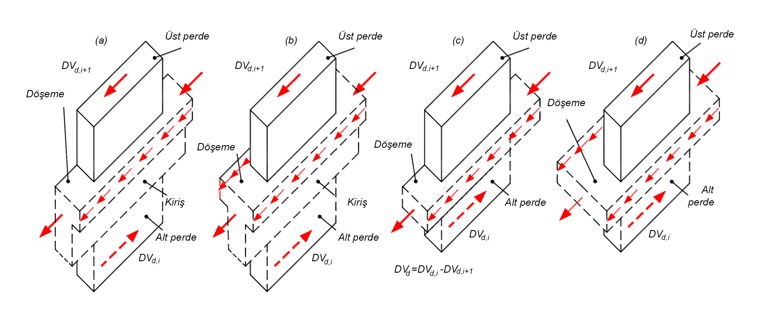
In the above picture, free body diagrams showing the shear forces transferred by beamed floor and non-beam floor systems connected to the curtain in a strong direction are shown. DV d is the shear force that occurs under the effects of earthquakes, which are increased with the Resistance Excess Coefficient D together with the vertical loads, and DV d is formed in the upper section of the wall below the i + 1 level, and the Resistance Excess with the vertical loads formed in the lower section of the wall above the i + 1 level. It expresses the shear force under earthquake effects, whose coefficient is increased by D. Here, the shear force generated due to earthquake loads and transferred from the floor to the curtains, (DV d) is calculated as the difference (DV d, i + 1 - DV d, i ) of the shear forces of the walls above and below the floor level . This shear force difference is met by the connection reinforcements A sb located in the slab, placed perpendicular to the shear plane and anchored to the curtain, and the transfer reinforcements A sa stuck from the slab or beams parallel to the shear plane and in a strong direction . These shear forces are available for every loading combination.
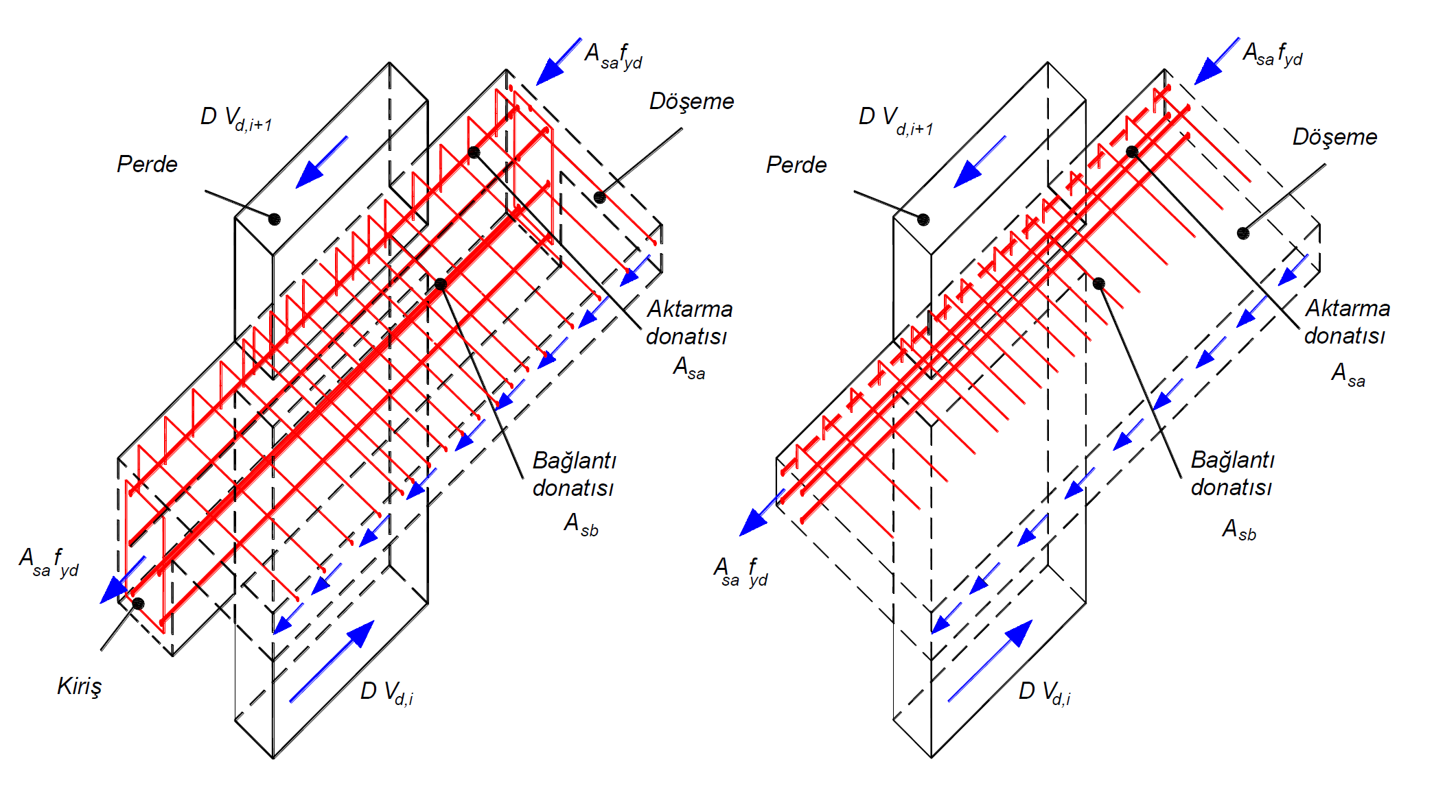
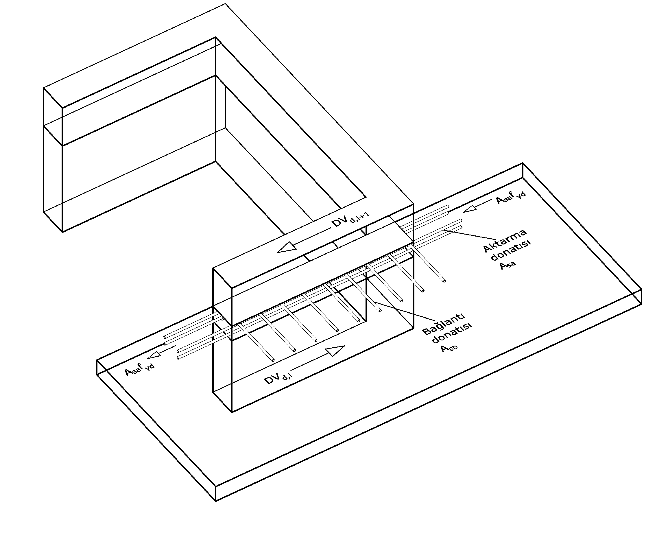
In the above picture, the transmission reinforcement A right and connection reinforcement A sb are shown for the joist floor system on the left . As can be seen, the connection reinforcements are the reinforcements perpendicular to the beams and shear walls, while A sa is the longitudinal reinforcement in the beams. In the picture to the right, transmission reinforcement A sa and connection reinforcement A sb are shown for systems with no beams . Since there is no beam stuck to the curtain from the strong axis, A sa consists of floor reinforcements.
2 h f yd refers to the sum of the axial tensile strength formed by the beam or slab reinforcement required for the process over from the screen indicated by the penetrating direction from both sides and strong resistance to bending. Here, the total area of the transfer reinforcement is expressed as A h . While calculating A hr , the area of reinforcement required for the flexural strength at the relevant point is subtracted from the total area of the reinforcements stuck in the curtain wall. If there is a floor or beam on one side of the curtain, this value is taken into account without multiplying by 2. A sa value, design yield strength of reinforcement, f yd The axial tensile strength of the remaining reinforcement required for bending strength is found when multiplied by,.
The process indicated by μA sb f yd is the shear friction strength created by the remaining floor reinforcement that is required for the flexural strength at the joint of floor and curtain. Here, A sb value is obtained from all reinforcement areas in the combination of slab and curtain, by the difference of the area of reinforcement required for the bending strength in this region. In addition , in the calculation of A sb , if a beam is stuck to the curtain from the strong line of the wall, these beams and the reinforcements in the slab joints are also taken into consideration. The μ coefficient is expressed as the friction coefficient and is calculated according to TS500. μA sb value design yield strength of reinforcement, f ydWhen multiplied by, there is the shear friction strength value. In the connection reinforcement calculation, if there are beams stuck to the curtain from the strong axis, the reinforcements between these beams and the floor are also taken into consideration. In these beams, the load will be transferred with the reinforcements to be added to the body area and the pressure stress that the beam can meet. Slab gaps and additional reinforcements defined for the slab are taken into consideration in the calculation of the connection reinforcements.
Article 7.11.5 TBDY according to the curtain or curtain rod from the floor to be transferred in accordance strong earthquake forces, DV d , 2 h for yd and μ to the SB f yd must not exceed the sum of the resistance. In this case;
DV d = (DV d, i + 1 - DV d, i ) <μA sb f yd + 2A sa f yd
condition must be met. This check is made for all loading combinations and the most unfavorable condition is taken into account.
In polygon walls , control is made according to TBDY Article 7.11.5 , taking into account the shear force on each arm. The shear section is defined at the center of gravity so as to provide the three-dimensional rigid body movement condition of the polygon shear finite elements, and the values obtained from the shear finite element results of the relevant loading combination are collected at this center of gravity and the internal forces of the polygon curtain are obtained. The shear force on each arm of polygon curtains is distributed appropriately in proportion to the shear areas by using the shear force calculated at the center of gravity, and the shear force coming to each arm is found for polygon curtains.
After the shear force on each arm is found, the shear force DV d, i + 1, calculated under the effects of earthquake, of the polygon shear arm above the slab level with the vertical loads and the Strength Excess Coefficient D , and the polygon shear arm below the slab level with vertical loads. The calculated force DV d, i is found under the effects of earthquakes with the coefficient D increased . That due to seismic loads for each pitch arm and to be transferred to the screen from the floor shear force (DV d ) The difference between the cutting forces and bottom of the curtain above the floor level (DV d, i + 1 - DV d, i ) was calculated.
In buildings with A2 and A3 type irregularities, according to Article 3.6.2.2 of TBDY , floor floors are modeled with shell finite elements to show that they can safely transfer earthquake forces between vertical bearing system elements in their own planes. A2 and A3 type irregularities create discontinuities in the floors and these discontinuities cause the slab stresses to grow at certain points. The following picture shows the gaps in the plan plane and the variation of the slab in-plane shear stresses. As can be noticed in the picture, stress concentrations occur at the points where the floor gaps are located.
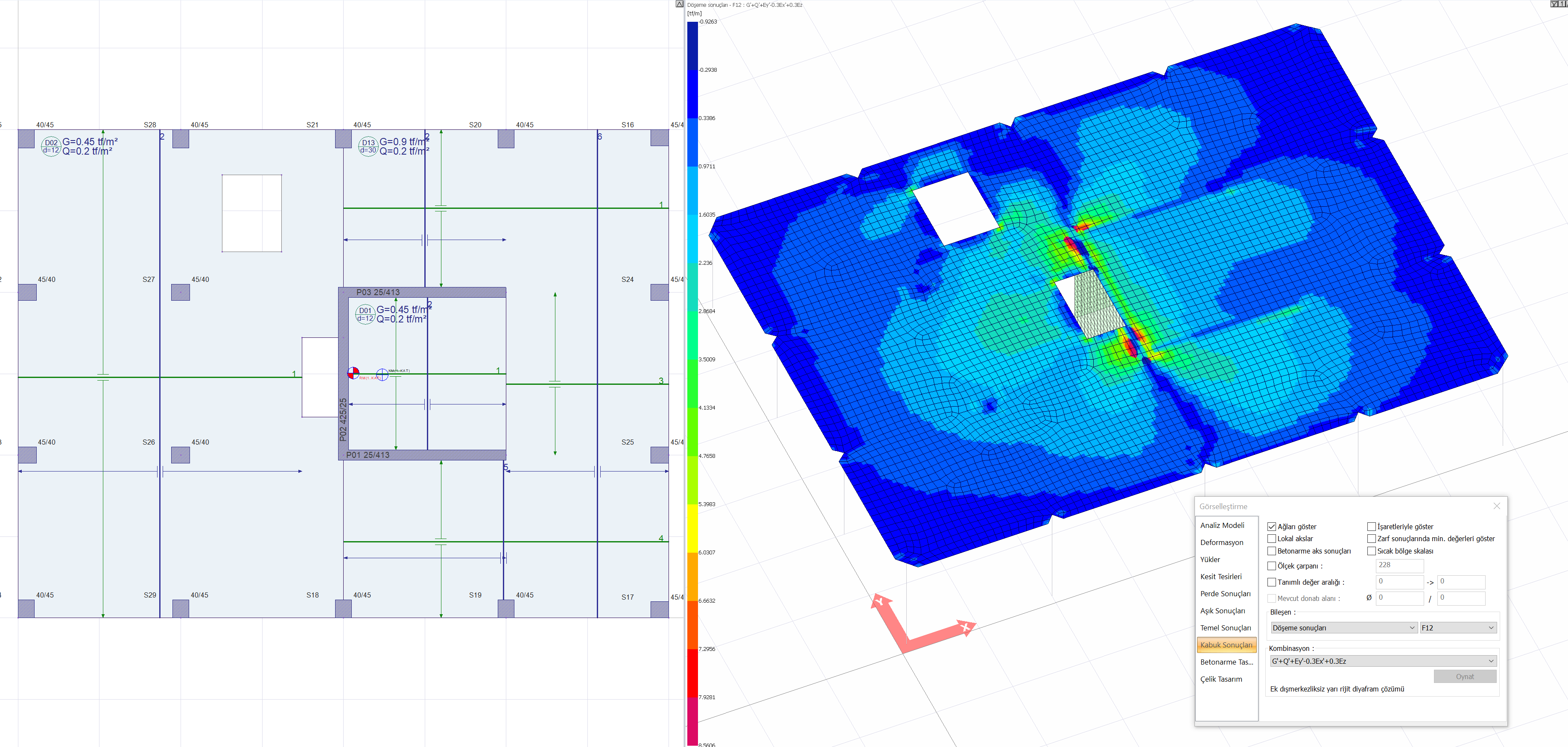
These agglomerations mean that the shear force transferred from the slab to the curtain is met with small areas outside the gap under the control of TBDY Clause 7.11.5 (DV d, i + 1 - DV d, i ). In this case, since the amount of connection reinforcement A sb will decrease considerably, the control of TBDY Article 7.11.5 becomes critical in buildings with A2 and A3 type irregularities .