
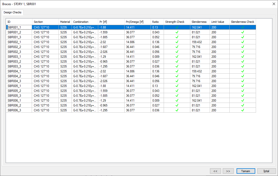
Steel brace design results and inadequacies of steel braces are displayed in the Braces dialog. The diagonals dialog displays the axial compressive strength ratio, slenderness control, and design ratio.
The Location of Braces Dialogue
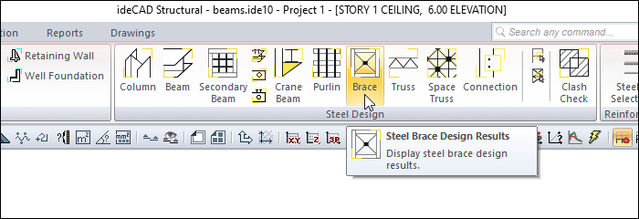
After the analysis is done, you can access it by clicking the Brace command under the Steel Design heading in the ribbon menu Analysis and Design tab .
Braces
|
Specifications |
|---|
|
ID 
It is the name of the brace members in the plan. |
|
Section 
It is the section used in brace members. |
|
Material It is the material used in brace members. |
|
Combo 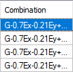
It is the load combination that produces the most unfavorable axial capacity ratio. |
|
Pr 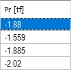
It is the largest axial force calculated using load ratings among the elements forming the brace. |
|
Pn/Omega 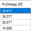
Among the elements forming the brace, the most negative is the safe axial strength. |
|
Ratio It is the axial capacity ratio. |
|
Strength check 
It is an information box whose sign changes according to the presence or absence of negativity in the brace section. |
|
Slenderness 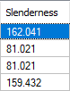
It is the slender value of brace members. |
|
Limit value 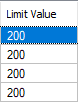
The maximum permitted slenderness of brace members. |
|
Slenderness check 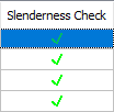
It is an information box whose sign changes according to whether the delicacy limit is exceeded or not. |
|
Previous The cursor moves to the previous line. |
|
Next The cursor goes to the next line. |
|
OK It saves the changes made and closes the dialog. |
|
Cancel Closes the dialog without saving the changes made. |
|
Summary Information The summary information about the line where the cursor is located is given in the name of the dialog in story, pose format. 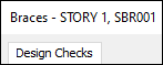
For example, STORY 1, SBR001 |
|
Using the Shift key In this tab, you can select more than one row with the Shift key, enter a value by double-clicking any cell whose value is open to change, and make that value apply to all selected rows. |
|
Using the Ctrl key Ctrl key selects the lines in between one by one. |
Next Topic
Related Topics