
Symbols
D = Strength coefficient
hi = ith floor height
I = Building importance factor
R = Bearing system response coefficient
Sae (T) = Horizontal elastic design spectral acceleration [g]
SaR (T) = Reduced design spectral acceleration [g]
SDS = Design spectral acceleration coefficient for short period [dimensionless]
SD1 = Design spectral acceleration coefficient for 1.0 second period [dimensionless]
T = Natural vibration period [s]
TA = Horizontal elastic design acceleration spectrum corner period [s]
TB = Horizontal elastic design acceleration spectrum corner period [s]
TL = Transition period to the constant displacement region in the horizontal elastic design spectrum [s]
ui = For any column or wall, Reduced displacement at i th floor
Δi = Displacement difference between two consecutive stories for any column or wall
δi = Effective relative storey drift for columns or walls at ith floor
δi,max = Effective relative storey drift for columns or shear walls on the ith floor of the building
λ = Empirical coefficient used to limit the relative storey drifts
κ = Differential coefficient used for reinforced concrete and steel load-bearing systems
-
For columns and shearwalls on any ith floor of the building in both horizontal earthquake directions, the maximum value of the effective relative storey drifts inside the storey δi,max must obey the conditions given in TBDY 4.9.1.3.
-
The coefficient λ mentioned in TBDY 2018 4.9.1.3 is the ratio of DD-3 earthquake ground motion elastic design spectral acceleration to DD-2 earthquake ground motion elastic design spectral acceleration for the dominant vibration period in the earthquake direction of the building. The coefficient κ is taken as 0.5 for steel buildings.
-
Detailed information about the relative story drift calculation is located in Calculation and Control of Relative Story Displacements.
-
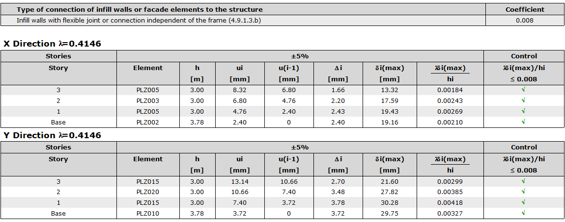
For the building, limitation has been selected in case of flexible joint or connection between the structural system and the walls. According to this selection, κ=0.5 is taken for steel and the limit value is calculated as 0.008.
Calculation of Lambda Coefficient
DD-2 default values
SDS =0.565
SD1 = 0.164
Ta = 0.2*SD1 /SDS = 0.2*0.164/0.565 =0.058
Tb = SD1 / SDS =0.389 / 1.112 =0.290
DD-3 default values
SDS=0.221
SD1=0.068
Ta = 0.2*SD1 /SDS = 0.2*0.068/0.221 =0.00615
Tb = SD1 / SDS =0.155 / 0.475 =0.307
As a result of dynamic analysis, the dominant vibration period for X and Y direction is determined by choosing the largest modal participation rates compatible with the relevant direction.
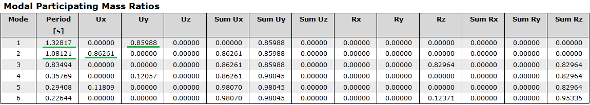
Modal for x direction → T=1.08011 sec
Modal for y direction → T=1.32680 sec
Calculation of Sae (T) values
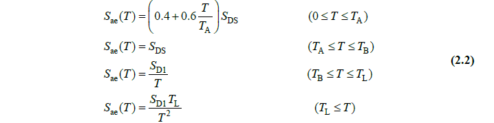
Calculation for X Direction
DD-2
T=1.08011 sn için
Ta= 0.058 < Tb= 0.29 < T=1.08011 -> Sae(T)=SD1/T = 0.152
DD-3
T=1.08011 sn için
Ta= 0.068 < Tb=0.307 < T=1.08011 -> Sae(T)=SD1/T= 0.063
Lamda = 0.063/ 0.152=0.4145
Calculation for Y Direction
DD-2
T= 1.32680 sn için
T=0.058> Tb=0.29< T=1.32680 -> Sae(T)=SD1/T= 0.164/ 1.32680=0.1236
DD-3
T=1.32680 sn için
T=0.068> Tb=0.307< T=1.32680 -> Sae(T)=SD1/T= 0.068/ 1.32680=0.05125
Lamda = 0.05125 / 0.124=0.0.4146
NOTE: Since all T values in both directions are greater than Tb, the lambda coefficient is actually equal to the ratio of SD1 parameters of both ground motion levels.
-
The values calculated by the program are as follows:
-
First of all, it is necessary to determine the column with the highest horizontal displacement in EX loading for each floor. For doing this, please go to perspective screen - view analysis model - deformations - EX load. At each floor, X-direction displacement of the column-beam joint is read and the difference between them is checked. The largest value in the story is used in the calculation of the relative storey drift.
-
This value read is the raw value. According to TBDY 2018, the raw value should be increased according to the equivalent earthquake load increase coefficient.
-
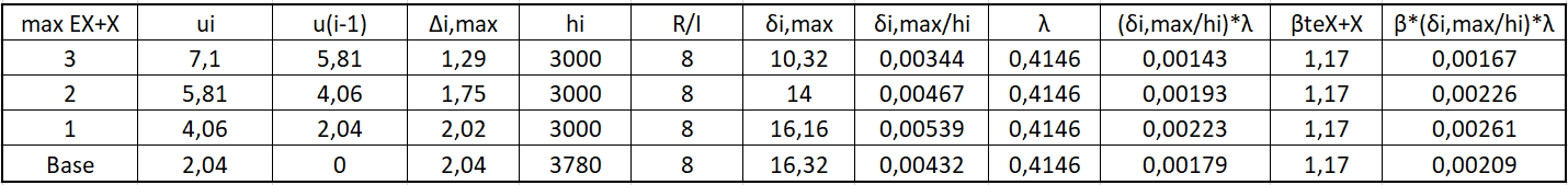
Due to the large size of the building, this process was not carried out, and the relative storey drift calculation is summarized in the table below, using the ∆i value directly included in the earthquake code report. In the table below, only X + 5% is checked. The point to be considered here is that these results should be increased with Magnification factor.
Next Topic