
The brace center connection is formed by bolting and welding the steel brace member to the column, beam or column-to-beam connection point by bolting and welding. Bolt control, weld control, plate control and connection application limits control are performed automatically according to the placement of the elements of the connection. Brace center connection design is made automatically according to the Design, Calculation and Construction Principles of Steel Structures (ÇYTHYEDY) or AISC 360-16 regulations and a connection report is created.
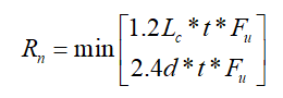
In the brace center connection calculation, horizontal and vertical bolt distances, butt plate weld thickness, continuity plate weld thickness and application limits are checked under geometry control. In strength control, cross bolt slip, plate bolt hole crushing, ski control, Whitmore section buckling, plate pressure leakage are checked.
Connection Geometry
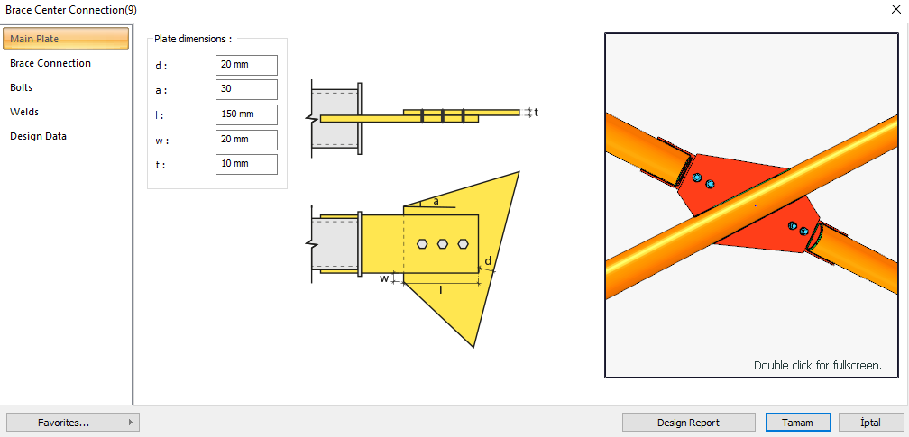
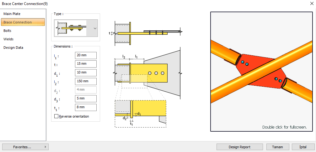
Brace - Gusset Connection
Geometry Checks
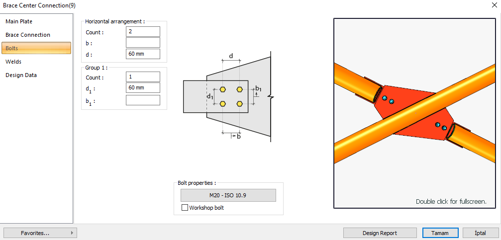
Bolt Spacing
|
s min ≥ 3d |
ÇYTHYEDY 13.3.6 |
|
|
|
s |
60 mm |
|
|
|
d |
20 mm |
s =60 mm > smin = 3*20=60 mm |
√ |
Horizontal Edge Distance
|
L eh ≥ L e- min |
ÇYTHYEDY 13.3.7 |
|
|
|
L eh |
57 mm |
|
√ |
|
L e- min |
26 mm |
Minimum distance check according to Table 13.9 |
√ |
Vertical Edge Distance
|
L ev ≥ L e- min |
ÇYTHYEDY 13.3.7 |
|
|
|
L ev |
45 mm |
Conformity check for L eh ≥ 2d = 2 * 20 = 40 mm application |
√ |
|
L e- min |
26 mm |
Minimum distance check according to Table 13.9 |
√ |
Weld Size
|
a ≥ a min |
ÇYTHYEDY 13.3.7 |
|
|
|
a |
4 mm |
|
√ |
|
a min |
3.5 mm |
Table 13.4 |
√ |
Strength Checks
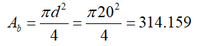
Bolt Shear at Brace
|
A b |
|
|
Fn |
|
|
Rn |
|
|
ΦRn |
|
|
Required |
Available |
Ratio |
Control |
|---|---|---|---|
|
169.593 kN |
212.058 kN |
0.800 |
√ |
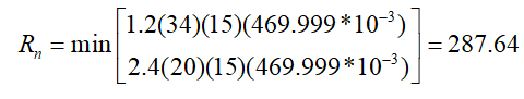
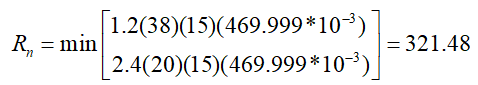
Bolt Bearing on Plate
|
d h |
20+2=22 mm |
|
|
Lc,edge |
|
|
|
Rn |
|
ÇYTHYEDY 13.3.13 Equation 13.14a and13.14b |
|
Rn-edge |
|
|
|
Lc,spacing |
|
|
|
Rn-spacing |
|
|
|
Rn |

|
|
|
ΦRn |
|
|
|
Required |
Available |
Ratio |
Control |
|---|---|---|---|
|
169.593 kN |
456.84 kN |
0.371 |
√ |
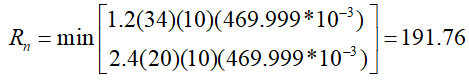
Bolt Bearing on Gusset
|
d h |
20+2=22 mm |
|
|
Lc,edge |
|
|
|
Rn |
|
ÇYTHYEDY 13.3.13 Equation 13.14a and13.14b |
|
Rn-edge |
|
|
|
Lc,spacing |
|
|
|
Rn-spacing |
|
|
|
Rn |

|
|
|
ΦRn |
|
|
|
Required |
Available |
Ratio |
Control |
|---|---|---|---|
|
169.593 kN |
304.56 kN |
0.557 |
√ |
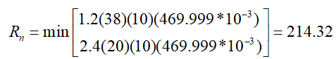
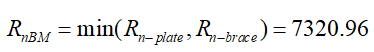
Weld Strength
|
Fe |
490000 kN/m2 |
|
w |
The weld thickness taken from the combination menu is 0.707 * w value. 4 / 0.707 = 5.658 mm |
|
F u-plate |
469.999 N/mm2 |
|
F u-brace |
410 N/mm2 |
|
tplate |
15 mm |
|
t brace |
15 mm |
|
lw |
150 mm |
|
R nw |

|
|
Rn-plate |
|
|
Rn-brace |
|
|
RnBM |
|
|
Rn |
|
|
ΦRn |
|
|
Required |
Available |
Ratio |
Control |
|---|---|---|---|
|
169.593 kN |
529.2 kN |
0.320 |
√ |
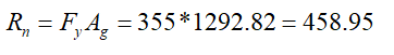
Whitmore Section Compression Yield
|
K |
0.65 |
|
|
L |
0 mm |
|
|
r |
2.887 mm |
|
|
KL / r |
0 |
|
|
Fy |
355 N/mm2 |
|
|
Ag |
1292.82 mm2 |
|
|
Rn |
|
ÇYTHYEDY 13.20 |
|
ΦRn |
|
|
|
Required |
Available |
Ratio |
Control |
|---|---|---|---|
|
169.593 kN |
413,056 kN |
0.411 |
√ |
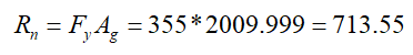
Gusset Compression Yield
|
K |
0.65 |
|
|
L |
65 mm |
|
|
r |
4.33 mm |
|
|
KL / r |
9.76 |
|
|
Fy |
355 N/mm2 |
|
|
Ag |
2009.999 mm2 |
|
|
Rn |
|
ÇYTHYEDY 13.20 |
|
ΦRn |
|
|
|
Required |
Available |
Ratio |
Control |
|---|---|---|---|
|
169.593 kN |
642,195 kN |
0.264 |
√ |
Next Topic
Related Topics