
Analysis, design and code requirements check results of slabs with or without beams are displayed in the Slab Reinforcements dialog. In the Slab Reinforced dialog, straight and additional reinforcement information of the slab calculation axises are given.
Location of Slab Reinforcements Dialogue
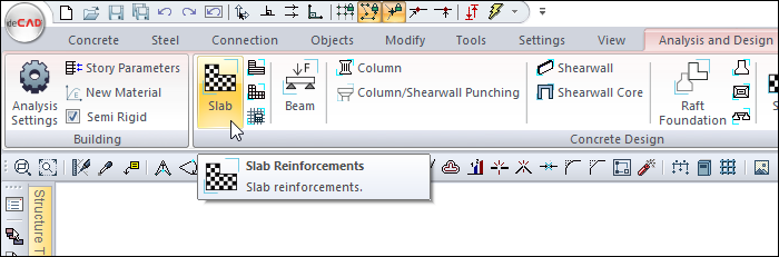
After analysis, you can access it by clicking the Slab command under the Concrete Design title of the ribbon menu Analysis and Design tab .
General Specifications of Slab Reinforcements Dialogue
|
Summary Information The summary information about the line where the cursor is located is given in the name of the dialog in the format of Story, Name, Calculation Axis No, Operation Type, Rebar type. 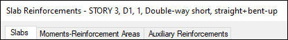
For example, Story 3, D1, 1, Double-way short, straight + bent-up |
|
Using the Shift key In this tab, you can select more than one row with the Shift key, enter a value by double-clicking any cell whose value is open to change, and make that value apply to all selected rows. |
|
Using the Ctrl key Ctrl key, on the other hand, selects the lines in between one by one. |
|
All Stories It lists the slabs on the screen throughout the entire story. |
|
Show horizontals It displays the horizontal rebars in the slabs by filtering, the vertical rebars are hidden, not shown in the list. |
|
Show verticals It displays the vertical rebars in the slabs by filtering, the horizontal rebars are hidden, not shown in the list. |
|
Select Selects the object on the line with the cursor. When the concrete dialog is closed, you can take action for the selected element. |
|
Previous The cursor moves to the previous line. |
|
Next The cursor goes to the next line. |
|
Filter
It is used to define certain conditions and filter only the elements that satisfy that condition. |
|
Ok It saves the changes made and closes the dialog. |
|
Cancel Closes the dialog without saving the changes made. |
Insufficiency Code Description and Recommended Solution
|
Insufficiency Code |
Description |
|---|---|
|
Min |
The slab section does not satisfy the minimum thickness requirement according to the design code.
|
|
Çd |
The slab behaves as a doubly reinforced section. Double reinforcement is not permitted in slab design, hence this warning.
|
|
S |
The slab does not meet the serviceability deflection limits specified in the design code.
|
|
As(–) |
The provided reinforcement area is insufficient. An adequate bar diameter may not have been selected.
|
|
Ç |
Per TBDY 2018 Clause 7.11.3, the slab’s tensile stress exceeds permissible limits.
|
|
K |
Per TBDY 2018 Clause 7.11.3, the slab’s shear stress exceeds permissible limits. Recommended action: Identify the critical shear region in the report and increase reinforcement (e.g., add shear reinforcement) or increase slab thickness. |
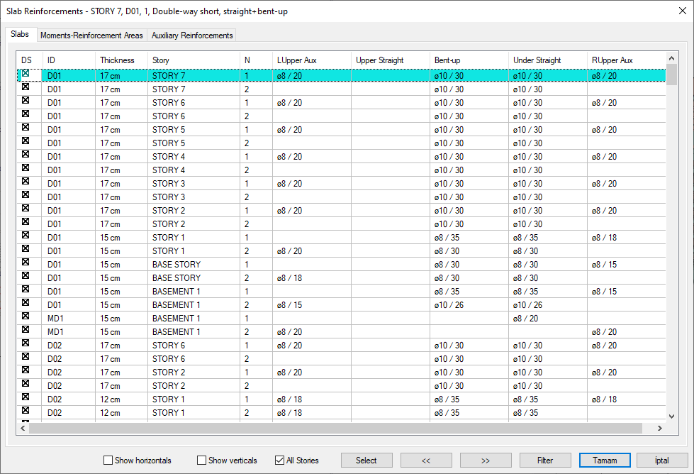
Slabs Tab
Slabs are listed according to the concrete account axis. Since there can be more than one concrete calculation axis in a slab, the concrete results will be listed with as many lines as the number of calculation axes available in the slab.
|
Specifications |
|---|
|
DS It is the rebar fixing column. If marked, the rebars are fixed. DS is automatically marked when changes are made to the slab rebars and the rebars remain fixed even if the slab is made of concrete. If DS is not marked, the rebars are determined again after the analysis according to the rebar selection conditions. |
|
ID 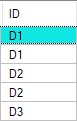
It is the name of the story that appears in the plan. With the dialog open, double click the name cell to find the slab in the plan. (D1, D2, D10 etc.) In case of negativity, a term about negativity is added next to the name of the record. For example, D101 (Min) will appear. |
|
Thickness 
The thickness of the slab appears in this cell. |
|
Story 
The name of the story where the slab is located appears in this cell. |
|
N It is the number of concrete calculation axis. (1,2,3,4 etc.) There can be more than one concrete calculation axis in the same slab. Slabs with the same name appear one under the other with the numbers of different account axes. From the N column, you can follow the direction of the calculation axis. |
|
L upper aux 
The diameter and the spacing in cm of the additional rebar calculated above the left support section on the relevant concrete calculation axis are shown. If double clicked on the cell, the diameter and spacing of the rebar can be changed. |
|
Upper straight 
It is the diameter and interval in cm of the rebar located above the slab section in the relevant concrete calculation axis. The diameter and spacing of the rebar can be changed by double clicking on the cell. 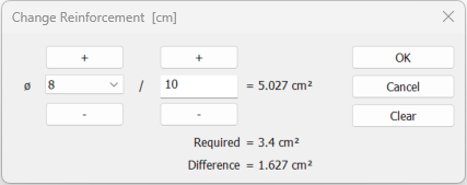
If the reinforcement type is selected as upper + under straight reinforcement, the required and available reinforcement area calculations are made and the difference is shown. |
|
Bent-up 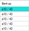
It is the diameter and interval in cm of the pleat rebar with slab on the relevant concrete calculation axis. The diameter and spacing of the rebar can be changed by double clicking on the cell. |
|
Under straight 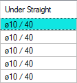
It is the diameter and interval in cm of the rebar located under the slab section on the relevant concrete calculation axis. The diameter and spacing of the rebar can be changed by double clicking on the cell.
If the reinforcement type is selected as upper + under straight reinforcement, the required and available reinforcement area calculations are made and the difference is shown. |
|
R upper aux 
It is the diameter and interval in cm of the additional rebar calculated above the right support section in the relevant concrete calculation axis. The diameter and spacing of the rebar can be changed by double clicking on the cell. |
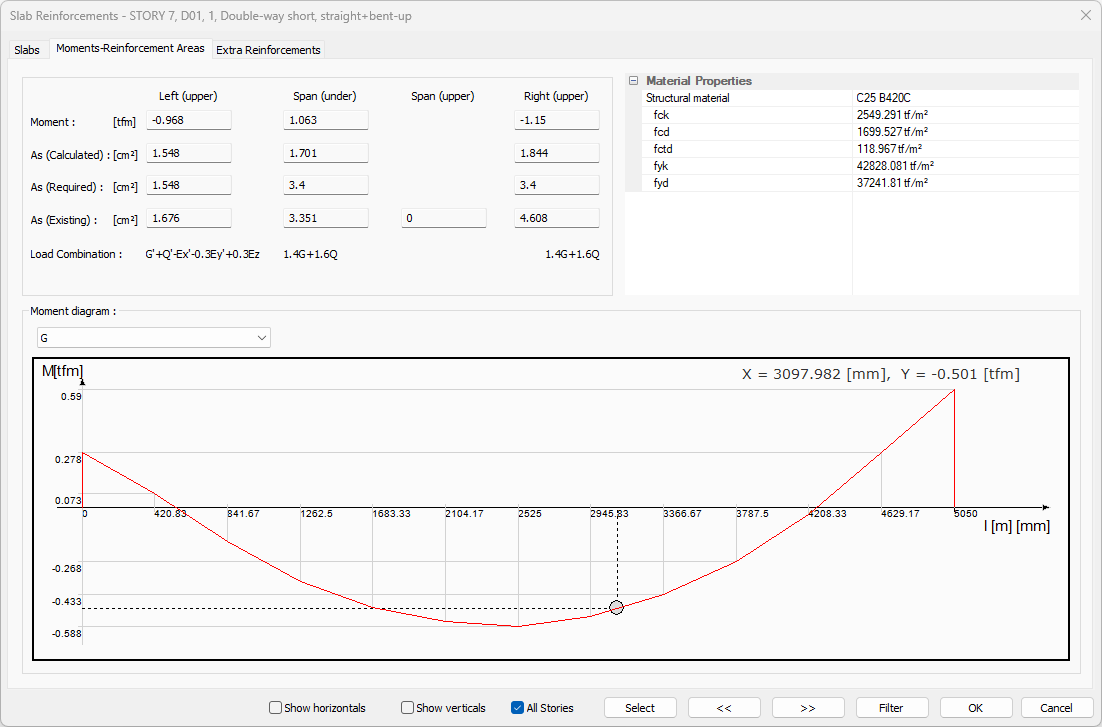
Moments - Reinforcement Areas Tab
|
Specifications |
|---|
|
Left (upper) 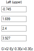
Defines the upper part of the section belonging to the left support of the slab for the investigated concrete calculation axis. |
|
Span (under) 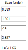
It defines the lower part of the section in the slab opening in the analyzed concrete calculation axis. |
|
Span (upper) 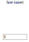
It defines the upper part of the section in the slab opening in the analyzed reinforced concrete calculation axis. |
|
Right (upper) 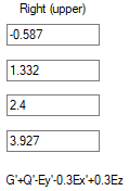
It defines the upper part of the section belonging to the right support of the slab in the analyzed concrete calculation axis. |
|
Moment The design moment value that is taken as basis in concrete design is given. |
|
As (Calculated) It is the area of rebar found for a width of 100 centimeters from the design moment. |
|
As (Required) It is the rebar area calculated from the design moment and the one that is greater than the rebar area to be placed as per the regulation. |
|
As (Existing) It is the total rebar area value available in the section after the rebar selection. |
|
Load combination You can examine the moment diagram by choosing the combination you want from the combination list. |
|
Structural material Shows the structural material of the slab. |
|
fck The characteristic of concrete is its compressive strength. |
|
fcd The characteristic calculation of concrete is its compressive strength. |
|
fctd The characteristic calculation of concrete is its tensile strength. |
|
Rebar fyk Reinforcement is the yield strength of rebar. |
|
fyd It is the calculation strength of rebar steel. |
|
Moment diagram The moment diagram according to the selected combination is displayed on the analyzed calculation axis. When you move the mouse over the moment diagram, the position of the cursor on the diagram is shown. X represents the Y moment value for the left distance. 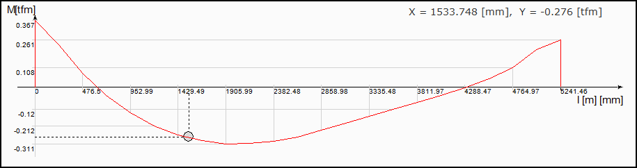
|
Extra Reinforcements Tab
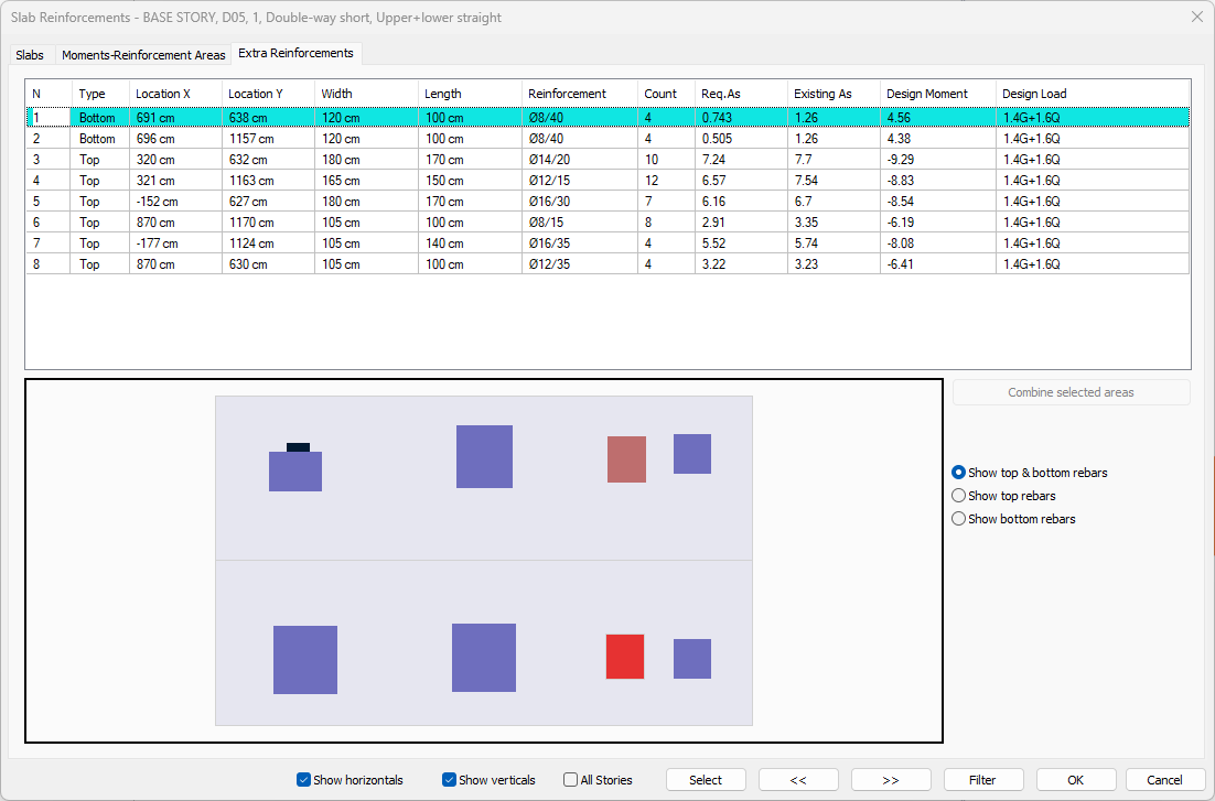
When flat rebar design is made on top and bottom for beams and non-beam slabs, the additional diameter and number are specified to cover the entire slab system. If the rebar calculation axis is selected as top and bottom straight, the program automatically creates additional zones on the supports required as a result of the plate analysis. After analysis and concrete design, the diameter and number of additional rebars are determined and listed on this tab.
In the tab, detailed information about the additional rebar is given in the table, and in the schematic plan view, the information about the area of the additional rebar is given. Blue areas represent upper additional rebar zones, red areas represent lower additional rebar zones.
|
Specifications |
|---|
|
N It is the number of the addition. It is assigned automatically by the program. |
|
Type Indicates the location of the additional rebar. If it is lower, additional rebar is at the bottom, if it is over, additional rebar is at the top. |
|
Location X 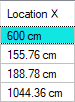
It is the distance of the region where the additional rebar is located to the global y-axis. |
|
Location Y 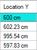
It is the distance of the region where the additional rebar is located to the global x-axis. |
|
Width 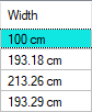
It is the width of the region where the additional rebar is located. |
|
Length 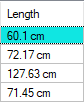
It is the height of the area where the additional rebar is located. |
|
Reinforcement 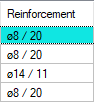
It is the diameter and range of the additional rebar to be placed in the region where the additional rebar is located. |
|
Count It is the number of additional rebar to be placed in the area where the additional rebar is located. |
|
Req. As 
In the area where additional rebar is located, it is the area of rebar greater than the amount of rebar that should be placed after the renar design or as required by the regulation. |
|
Existing As. 
It is the amount of rebar placed in the area of additional rebar. |
|
Design moment 
It is the design moment that gives the greatest rebar in the area where the additional rebar is located. |
|
Design load 
The most unfavorable loading type in which the design moment is calculated is written. |
|
Combine selected areas Selected additional rebar areas from the list are combined. |
|
Show top & bottom rebars If the option is selected, top and bottom additional rebars are shown. |
|
Show top rebars If the option is selected, top additional rebars are shown. |
|
Show bottom rebars If the option is selected, bottom additional rebars are shown. |
Next Topic
Related Topics