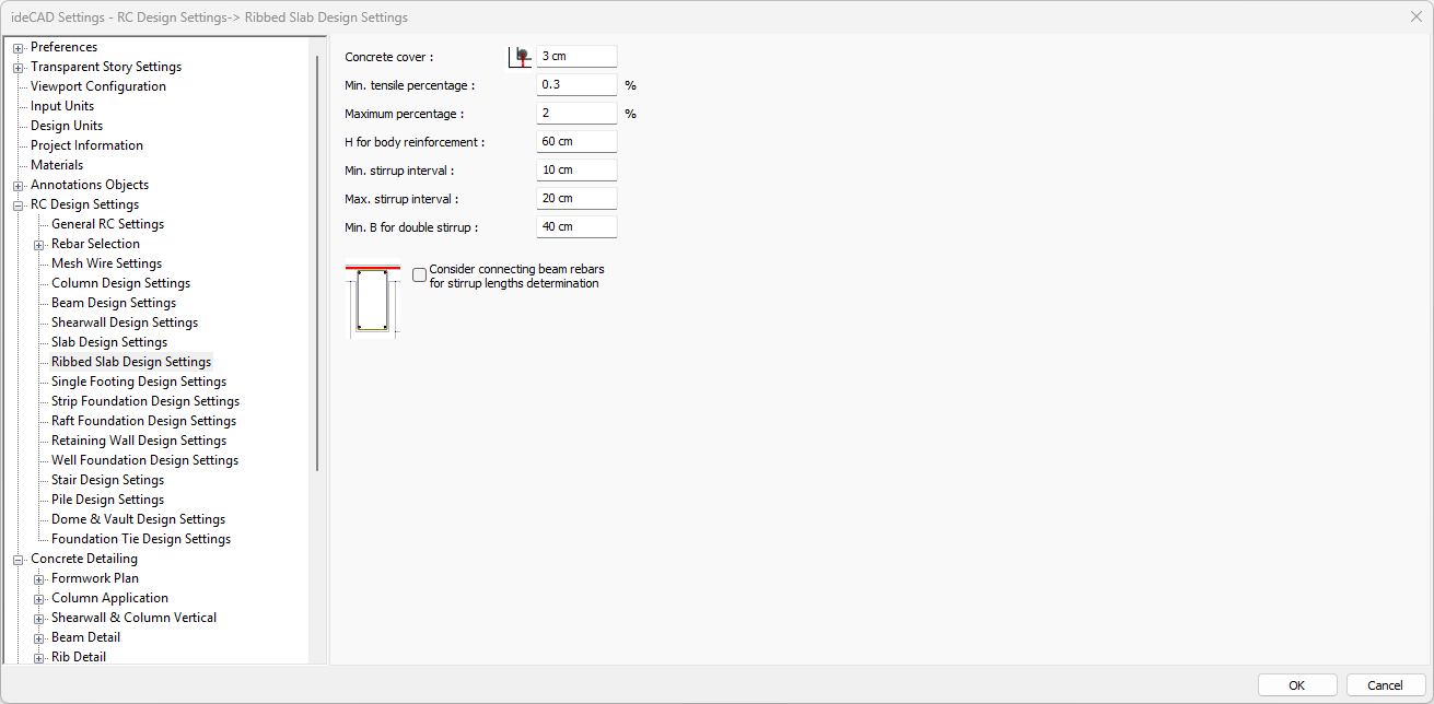
Ribbed Slab Design Settings Section
With the Ribbed Slab Design Settings, the design parameters used in the design of concrete ribbed and waffle slabs are determined. Concrete cover, maximum and minimum reinforcement interval, etc. parameters are determined from the rib-waffle parameters window.
Parameters denoted with “%” refer to the reinforcement ratio expressed as a percentage—that is, the ratio of the area of reinforcing steel to the gross cross‑sectional area of the concrete element, multiplied by 100.
For instance:
A minimum reinforcement ratio of 1% corresponds to a steel area equal to 1% of the concrete section.
Since a reinforcement ratio of 0.01 (i.e. 0.01 × 100) equals 1%, the value “1” should be entered for this parameter.
All percentage values must be entered as the ratio multiplied by 100. If your design software requires integer percentages, round to the nearest whole number.

Specifications |
|---|
Concrete cover  It is the distance from the center of gravity of the tensile or compression rebar inside the rib and waffle teeth to the outer face of the concrete. |
Min. tensile percentage  The percentage of rebar that determines the minimum rebar to be placed in the tension zone in the rib-waffle thread. The percentage value of the gross area of the rib-waffle specified in this parameter determines the minimum rebar area. In rib and waffle threads, this parameter is used at the bottom of the threads opening and at the top of the threads support. The minimum rebar area of the concrete element means that the gross section will not be less than the percentage value entered with this parameter. |
Maximum percentage  It is the rebar percentage that determines the maximum value of the tensile rebar (top rebar at the support, bottom rebar at the opening) to be placed on the rib-waffle thread. The percentage value of the rib-waffle gross area specified in this parameter determines the maximum rebar area. The maximum rebar area of the concrete element means that the gross section will not exceed the percentage value entered with this parameter. |
H for body reinforcement  If the height of the rib-waffle thread is more than the value specified in this parameter, 2 pieces of 10 body rebar are placed on the thread. |
Min. stirrup interval  In the program, the spacing of the stirrup to be placed on the rib-waffle tooth is selected not less than the value specified in this parameter. |
Max. stirrup interval  In the program, the spacing of the stirrup to be placed on the rib-waffle tooth is selected not to be more than the value specified in this parameter. |
Min. B for double stirrup  The width of the rib-waffle thread is compared with this parameter. As long as the width of the thread does not exceed the minimum width specified in this parameter, the threads are equipped with a double arm stirrup. Otherwise, they are equipped with 2 double-armed stirrups. |
Consider connecting beam rebars for stirrup lengths determination  When calculating the length of the gingiva, it is thought that it will be placed to surround the flat rebar at the bottom with the top mounting. When this option is checked, it is assumed that the flat rebars coming from the adjacent beam, if any, together with the top assembly are also included in the stirrup. As a result, the stirrup length is calculated with allowance for the rebars coming from the neighboring entrance at the top and the opening is drawn in that way. |
Next Topic
