
In this example, the deformation of a console rod element connected with a built-in support at one end under temperature loading and the internal force value of a rod element with a fixed support at one end and a fixed support at the other end is calculated.
ideCAD Structural takes into account the loading situation caused by two different temperature changes and these temperature changes are considered separately.
|
Loading Model |
Compared size |
ideCAD Static |
Manual solution |
Percentage of error |
|---|---|---|---|---|
|
Model 1 - T1 |
UZ (in) |
0.0013 |
0.0013 |
0% |
|
Model 1 - T2 |
UZ (in) |
0.0026 |
0.0026 |
0% |
|
Model 2 - T1 |
Axial pressure (mode) |
22.62 |
22.62 |
0% |
|
Model 2 - T2 |
Axial pressure (mode) |
45.26 |
45.26 |
0% |
Geometric Properties and System Description
In this example, two first 10 inch long rectangular rod elements are used. One end of these rod elements is flush-mounted, the other rod element is defined as one end is fixed support and the other end is fixed support.
In the first system, the free joint displacement value will be calculated, in the second system the axial pressure force due to temperature change will be calculated.
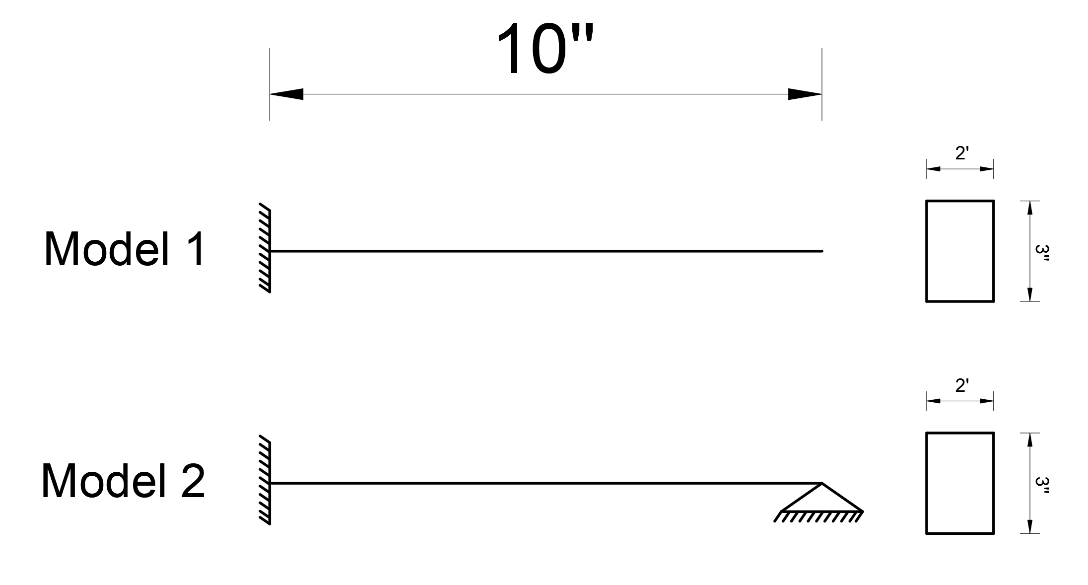
A rectangular section with a width of 2 inches and a height of 3 inches is used as a rod element.
The area of the rectangular cross section is calculated as A = 3 * 2 = 6 in 2 and the
moment of inertia I = (1/12) * (2 * 3 3 ) = 4.5 in 4
.
The modulus of elasticity of the material used was determined as E = 29000 k / in 2 and the thermal expansion coefficient ε = 0.0000065 (1 / o C).
You can reach the file with all loading statuses defined below.
Loading Statuses and Results
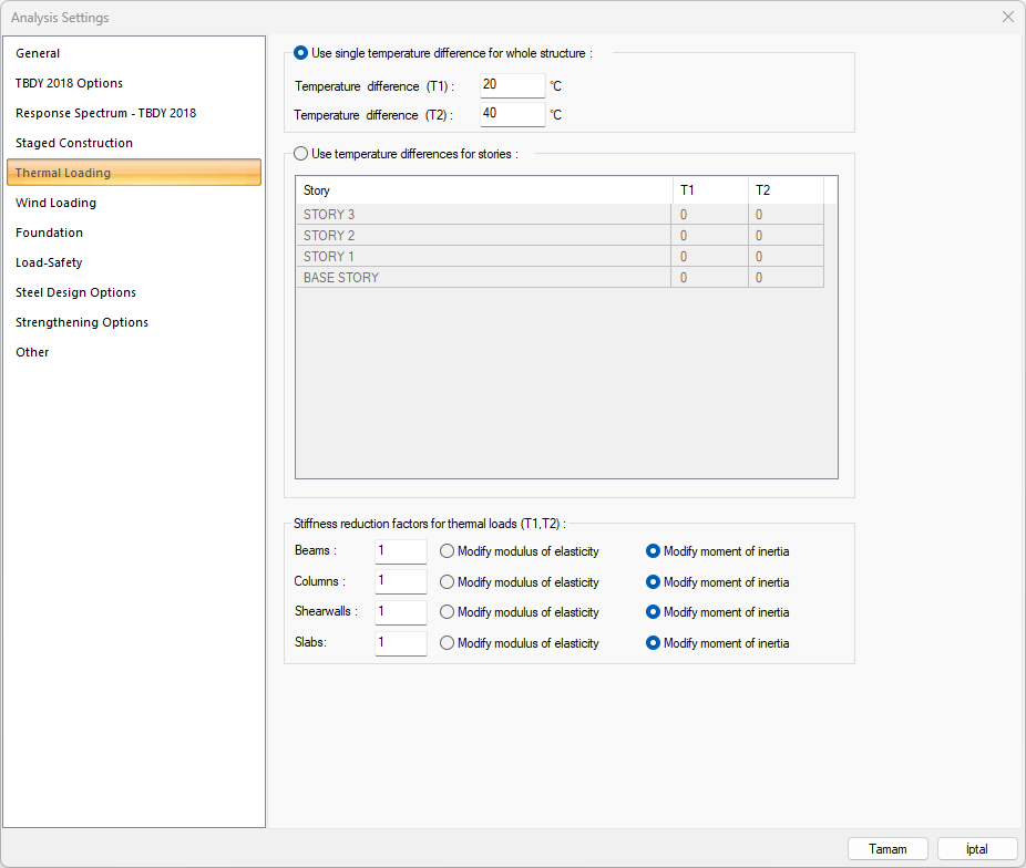
Two different temperature differences were created for the loading condition, T1 = 20 o C and T2 = 40 o C. The reduction factor will not be used for temperature loads.
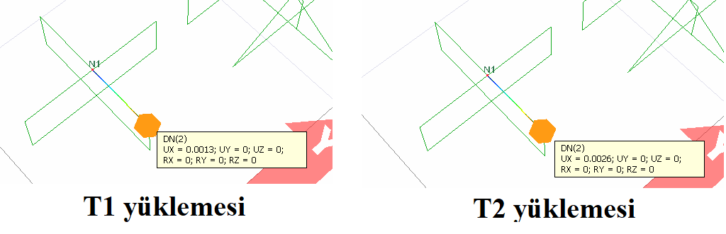
The displacement value at the node when temperature loading is applied in Model 1;
Δ = ε * t * L
can be calculated as. In this equation Δ is the joint displacement value, ε the thermal expansion coefficient and L is the element length. In this case, T1 = the value of the displacement at the temperature difference of 20 o C;
Δ T1 = ε * t * L = 0.0000065 * 20 * 10 = 0.0013 in
T2 = the displacement value at the temperature difference of 40 ° C;
Δ T2 = ε * t * L = 0.0000065 * 40 * 10 = 0.0026 in
calculated as.
The results of Δ T1 = 0.0013 and Δ T2 = 0.0026 are exactly the same with ideCAD Structural.
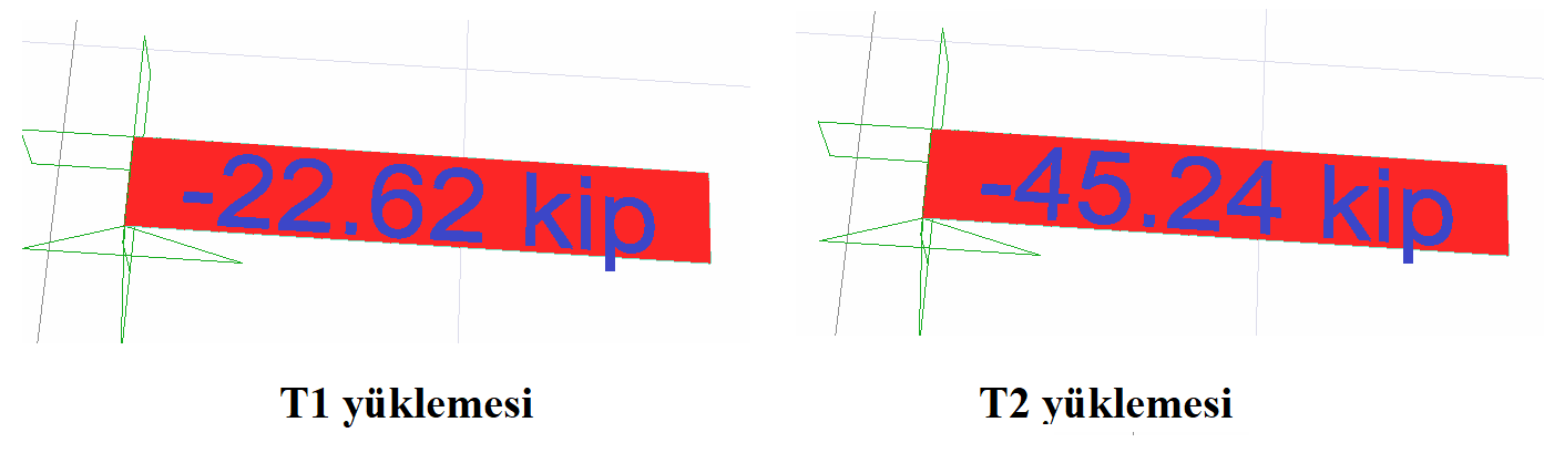
In Model 2, the concept of stiffness can be used to find the internal force value that occurs when temperature loading is applied. The extension stiffness of an element is calculated by the relation AE / L. In this case, using the values in Model 1 and the term extension stiffness, the value of the axial compressive force generated in the element;
N = Δ / (AE / L)
can be found by the relation. Here Δ is the deformation value taken from Model 1, A element cross-section area, E elasticity module and L element length. In this case, T1 = the value of the axial pressure force at the temperature difference of 20 o C;
N T1 = Δ T1 / (AE / L) = 0.0013 / (6 * 29000/10) = 22.62 kip
T2 = axial pressure force value generated at the temperature difference of 40 o C;
NT2 = ΔT2 / (AE/L) = 0.0026/ (6*29000/10) = 45.26 kip
was found as.
The results of N T1 = 22.62 kip and N T2 = 45.26 kip are exactly the same as for ideCAD Structural.
Next Topic