
How does ideCAD design steel connections subject to shear according to AISC 360-16?
-
Limit states of Bearing-Type connections are calculated automatically according to AISC 360-16.
-
The limit state of shear failure of bolts, limit state of bearing failure of plates, limit state of shear failure of plates, and limit state of ovalization of the bolt hole are calculated in bolted connection according to AISC 360-16.
Symbols
Ab: Non-threaded bolt web characteristic cross-sectional area
Ag: Gross area
An: Net cross-section area
Ae: Effective net cross-sectional area
Avg: Gross area under shear stress
Anv: Net area under shear stress
Ant: Net area under tensile stress
Aw: Cross-section web area
Cv: Coefficient of reduction for shear buckling
d: Characteristic diameter of the stem of the bolt (the diameter of the non-threaded stem of the bolt)
dh: Bolt hole diameter
Fnt: Characteristic tensile strength
F'nt: Reduced characteristic tensile stress obtained by considering the shear force effect
Fnv: Characteristic shear stress strength
frv: The greatest shear stress in the characteristic web area of the bolt
Fy: Structural steel characteristic yield strength
Fu: Structural steel characteristic tensile strength
Fyb: Bolt characteristic yield strength
Fub: Bolt characteristic tensile strength
nsp: Number of slip planes
s: Distance between bolt-hole centers
Le: The distance from the center of the bolt hole to the edge of the assembled element
t: Plate thickness
Rnt: Characteristic tensile strength
Rnv: Characteristic shear strength
Ubs: A coefficient considering the spread of tensile stresses
Design Criteria Under Shear
-
It is assumed that the web of the cross-section transfers all shear force.
-
There is no interaction between shear force and bending moment.
Shear Strength
In stiffened and unstiffened single and double symmetric cross-sections, the characteristic shear strength in the web plane is calculated as follows:
The coefficients for the I cross-section members are determined according to the slenderness ratio:
For webs of rolled I-shaped members with
The allowable shear strength is calculated as follows:
-
The design shear strength =
-
The allowable shear strength =
Bearing Type Connections
-
In bearing-type connections, the strength is determined according to the smallest one by checking two limit states.
-
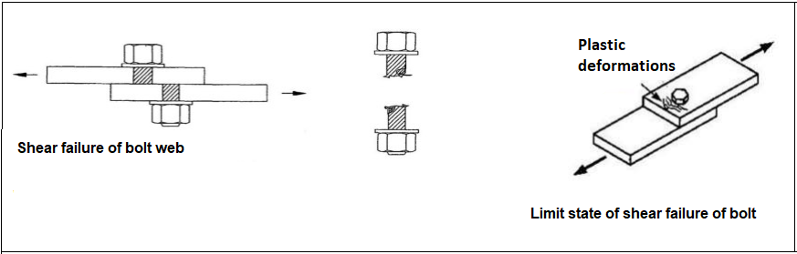
Shear failure of the bolt
-
Bearing failure of the plate
i) Ovalization of bolt hole
ii) Shear failure of the plate
Characteristic Tensile and Shear Strength of Bolts
-
Characteristic tensile strength Fnt of bolts is determined depending on the characteristic tensile strength of bolt material, Fub.
|
Bolt Grades |
Fyb [N/mm2] |
Fub [N/mm2] |
|---|---|---|
|
4.6 |
240 |
400 |
|
5.6 |
300 |
500 |
|
6.8 |
480 |
600 |
|
8.8 |
640 |
800 |
|
10.9 |
900 |
1000 |
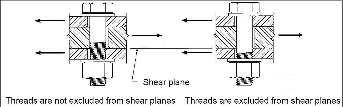
The characteristic shear strength of bolts, Fnv, is calculated in two different ways:
-
If the threaded web part of the bolt is in the shear plane, the following equation is valid:
-
If the threaded web part of the bolt is outside the shear plane, the following equation is valid:
Tensile and Shear Strength of Bolts and Threaded Parts
-
The characteristic tensile or shear strength of preloaded high-strength bolts, snug-tightened bolts, and threaded cross-sections are computed according to the rupture limit conditions under the tensile or shear effects.
The Computation for Bearing Type Connections
Bearing Limit States for the Plates (Bolt Holes)
-
Bearing, in other words, plastic deformations occur in the bolt stem and plate due to compression stresses between the bolt stem and the plate edge.
-
To calculate the bearing stress values between the bolt stem and the hole edge, the calculation is made with the assumption that the stresses are uniformly distributed on this surface under the effect of compression.
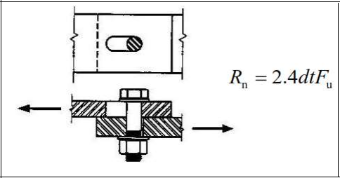
The Bearing of the Bolt Hole
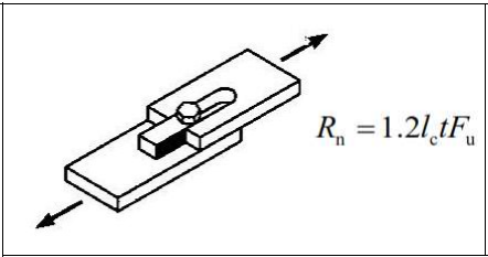
Tearout
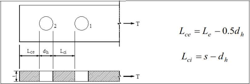
-
The characteristic bearing resistance Rn of a bolt hole is calculated based on the bearing limit state under the shear effect as follows:
-
Regardless of the direction of the load, for connections formed from standard and oversized holes, short and long slotted, or any other oval holes in which their longitudinal axis is parallel to the direction of the load:
-
For connections formed with long-slotted:
-
Depending on the regulation, safety coefficients are defined as follows:
Shear Resistance
-
The characteristic shear strength of the cross-section and connected members under shear load for yielding and rupture limit states, Rn, is calculated as follows:
Yielding Limit State
Rupture Limit State
Block Shear Limit State
-
The characteristic block shear strength, Rn, is calculated based on the yielding and rupture limit states along the shear surface or surfaces and the rupture limit states along the tensile surface.
Tensile Strength
-
The characteristic tensile strength of the cross-section and connected members under tensile stress is calculated for the yielding and rupture limit states as Rn shear effect as follows:
Yielding Limit State
Rupture Limit State