
-
Modal Capacity Curve is obtained automatically.
-
After the Modal Capstie Curve , the impulse curve is obtained automatically.
ICONS
a 1 (X,k) = modal pseudo-acceleration of the first mode modal single degree of freedom system at the kth push step for the earthquake direction [m/s 2 ]
d 1 (X,k) = (X) The modal displacement of the modal single degree of freedom system belonging to the first mode at the kth thrust step for the earthquake direction [m]
m tx1 (X,1) = (X) for the earthquake direction, which is determined in the first thrust step in the x-axis direction and remains unchanged throughout the thrust calculation. modal effective mass of base shear calculated according to constant mode shape [t]
m txk (X,k) = (X) modal effective mass of the base shear force calculated according to the constant mode shape renewed with the free vibration calculation at the kth thrust step in the x-axis direction for the earthquake direction [t]
u ix1 (X,k) = (X) for the earthquake direction The displacement [m]
Δa 1 (X,k) = (X) calculated in the x-axis direction at the i-th floor at the k-th thrust step is the modal pseudo-acceleration of the modal single degree -of- freedom system of the first mode at the k-th thrust step for the earthquake direction. increment [m/s 2 ]
Δd 1 (X,k) = (X) belonging to the first mode at the kth push step for earthquake modal single degree of freedom system 's modal displacement of [m]
Φ Nx1 (1) = N th layer on the first push is determined at step and push account never changed during the fixed mode shape "amplitude in the x direction
Φ Nx1 (k) = N-th floor The amplitude of the fixed mode shape determined in the first thrust step and renewed with the free vibration calculation in the kth thrust step , in the x direction
Γ 1 (X,1) = (X) fixed mode shape determined in the first thrust step for the earthquake direction and never changed during the thrust calculation modal contribution multiplier calculated according to
Γ 1 (X,k) = modal contribution factor calculated according to the variable mode shape renewed with free vibration calculation at each k th thrust step for (X) earthquake direction
ω 1 (k) = renewed at each k th thrust step first mode natural angular frequency [rad/s] found from free vibration calculation
TDY 5B.2.5 'in the manner described, k' th obtained in step push modal displacement increments expressed as a dimensionless one (X, k) using TDY Equation 5B.10 'calculated by the modal-called acceleration increment Δ A 1 (X, k) , of the previous step TDY is obtained as in Equation 5B.11 by summing with the values obtained at the end .

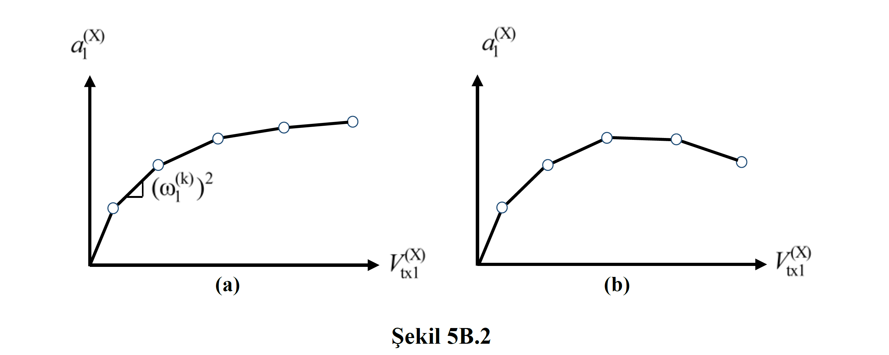
Thus, in the propulsion method with variable displacement distribution , a modal capacitance diagram whose coordinates are modal displacement – modal pseudo-acceleration is obtained without the need to plot the thrust curve . In this diagram , the slope of the line segment, which represents the step-by-step linear behavior at the kth push step between two successive hinge formations , is equal to 2 ( ω 1 (k) ) according to TDY Equation 5B.10 ( Figure 5B.2a ).

To find the building performance point, a modal capacitance diagram whose coordinates are modal displacement – modal pseudo-acceleration is used so that the displacement demand can be obtained using the Horizontal Elastic Design Spectrum . Each k th step push TDY Equation 5B.11 obtained by the spectral displacement d 1 (X k) and modal so-called acceleration a 1 (X, k) values TDY Equation 5B.3 and TBDY Equation 5B.4 coordinates using base is converted to a thrust curve with shear force-peak displacement .
However, since these equations ( TDY Equation 5B.3 and TDY Equation 5B.4 ) are written for the Constant Single Mode Propulsion Method , the terms in the equations must be written for the Variable Single Mode Propulsion Method .

Instead of the modal effective mass m tx1 (X,1) obtained in the first mode of the modal analysis performed in the initial step given in TDY Equation 5B.3 , the calculated mode shape is calculated according to the mode shape obtained from the free vibration calculation (modal analysis) made at each kth thrust step. The values of modal effective masses m ix1 (X,k) on the i th floor are used.

TDY Equation 5B.4 , the modal analysis made in the initial step given in the first mode (dominant mode) is the modal amplitude at the Nth floor Φ Nx1 (1), instead of the modal amplitude Φ Nx1 (1) , taking into account the stiffness change caused by the plastic hinges in each kth thrust step. The mode amplitude Φ Nx1 (k) in the N 'th floor obtained in the first mode of the modal analysis (dominant mode) is used. Similarly, the modal contribution factor obtained as a result of the modal analysis performed in the initial step is replaced by the value Γ 1 (X,1). The modal contribution factor Γ 1 (X,k) value calculated as a result of the modal analysis made by taking into account the change in stiffness caused by the plastic hinges in each kth pushing step is used.
Obtaining the performance point described in detail inDetermination of Modal Displacement and Performance Point (5B.3).