
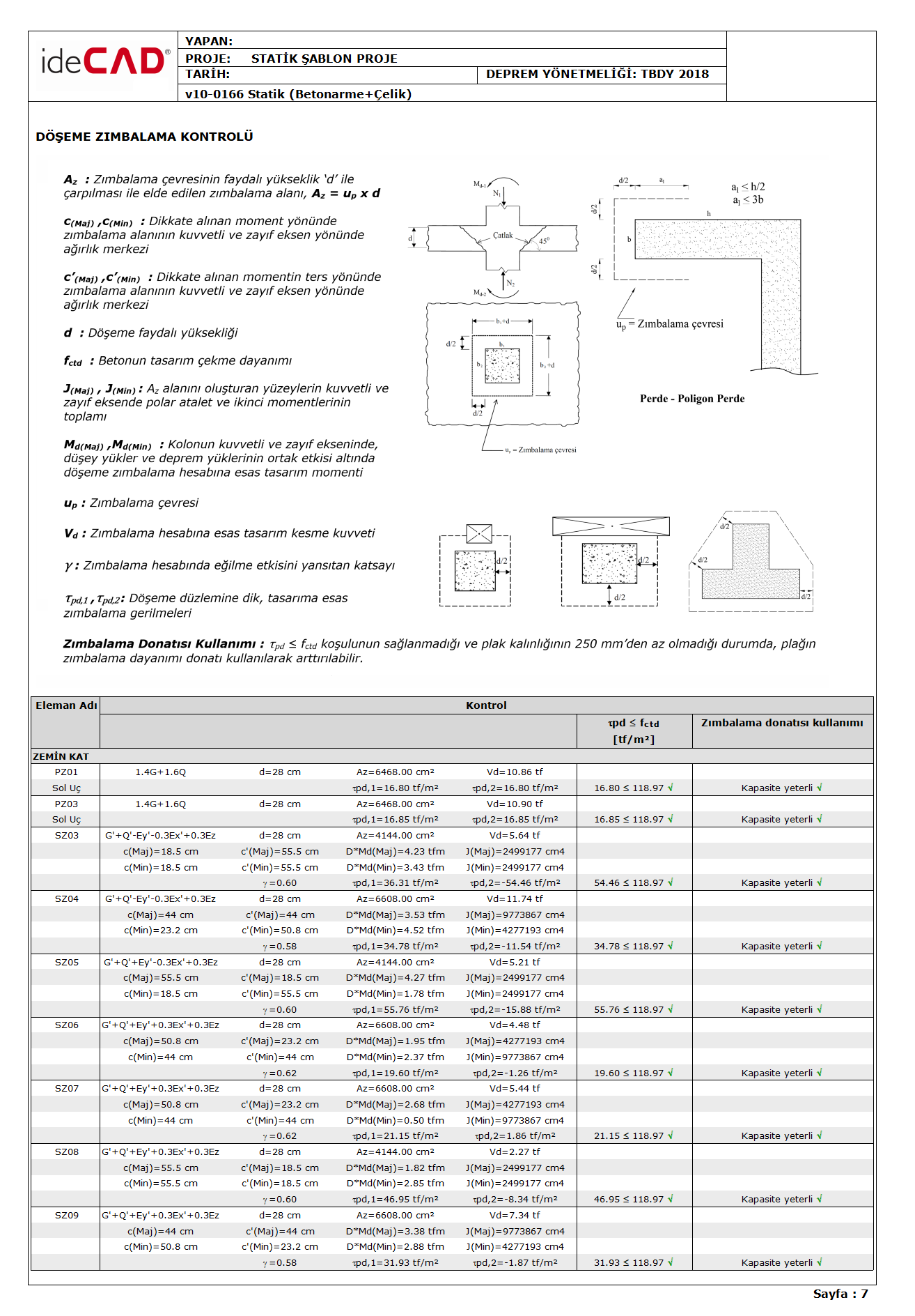
Punching Control is controlled in accordance with TBDY 7.11.8 , TBDY 7.11.9 , TBDY 7.11.10, TBDY 7.11.11, TBDY 7.11.12, TBDY 7.11.13 . In the picture below, there is an example of the floor punching control report made with ideCAD Structural.
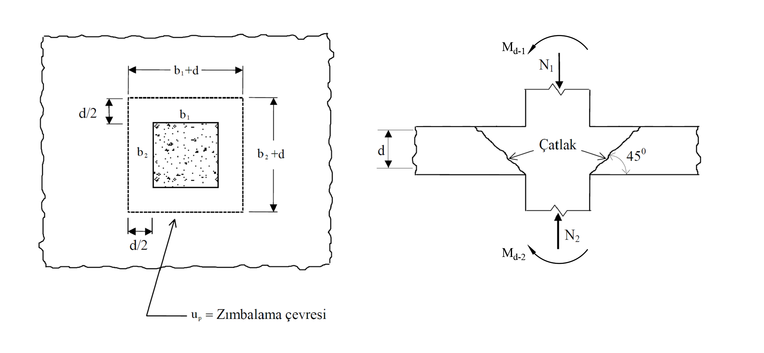
Punching control As specified in TBDY 7.11.8 , with the assumption that shear stresses in the slab change linearly with respect to the geometric center of the punch perimeter in the loading direction, the punching perimeter on the slab (u p will be made by calculating the idealized distribution of the shear stresses acting on the ), .
τ pd, 1 , τ pd, 2 : It expresses the punch stresses based on the design. Considering the effect of axial forces and bending moments, the slab is the largest and smallest punching stresses and is calculated with the equations shown below.
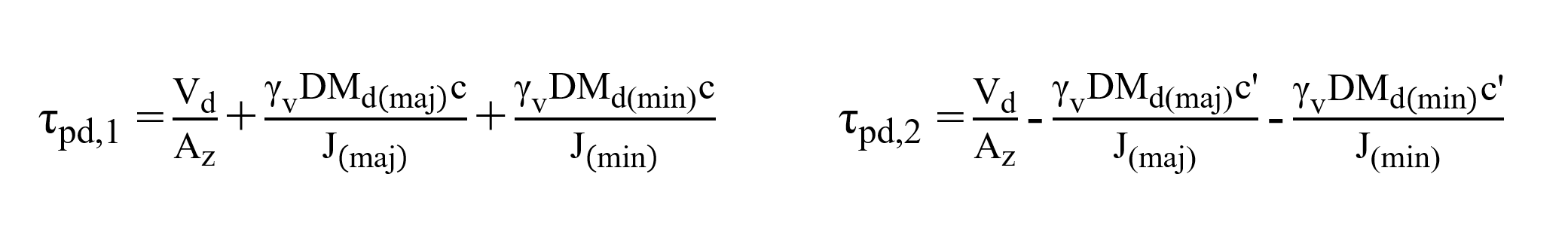
The punching stresses (τ pd, 1 , τ pd, 2 ) should not exceed the design tensile strength (f ctd ) of the concrete . τ pd, 1 , τ pd, 2 ≤ f ctd
f ctd : design tensile strength of concrete
V d : It is the design shear force value based on the punching calculation. It is calculated as the difference of axial pressure forces calculated under the combined effect of vertical loads and earthquake loads occurring in the regions above and below the slab level in columns or walls.
M d (maj) , M d (min) : It is the design moment calculated under the combined effect of gravity and earthquake loads in the strong and weak axis of the column and is the basis for the slab punching calculation. When calculating the punching stresses (τ pd, 1 and τ pd, 2 ), the bending moment values (M d (maj) , M d (min) ) that occur under the combined effect of earthquake loads calculated by taking into account the gravity loads and the Extra Strength Coefficient D are used.
A z : Stapling area. It is obtained by multiplying the punch perimeter by the slab useful height, d.
A z = u p xd
d: refers to the useful height of the floor. It is the value obtained by subtracting the floor cover from the thickness of the floor.
The punch perimeter (u p ) is the perimeter calculated at a distance d / 2 from the column or curtain surface. While calculating the punching perimeter, all of the floor spaces, corner or side column-curtain, polygon column situations are taken into consideration.
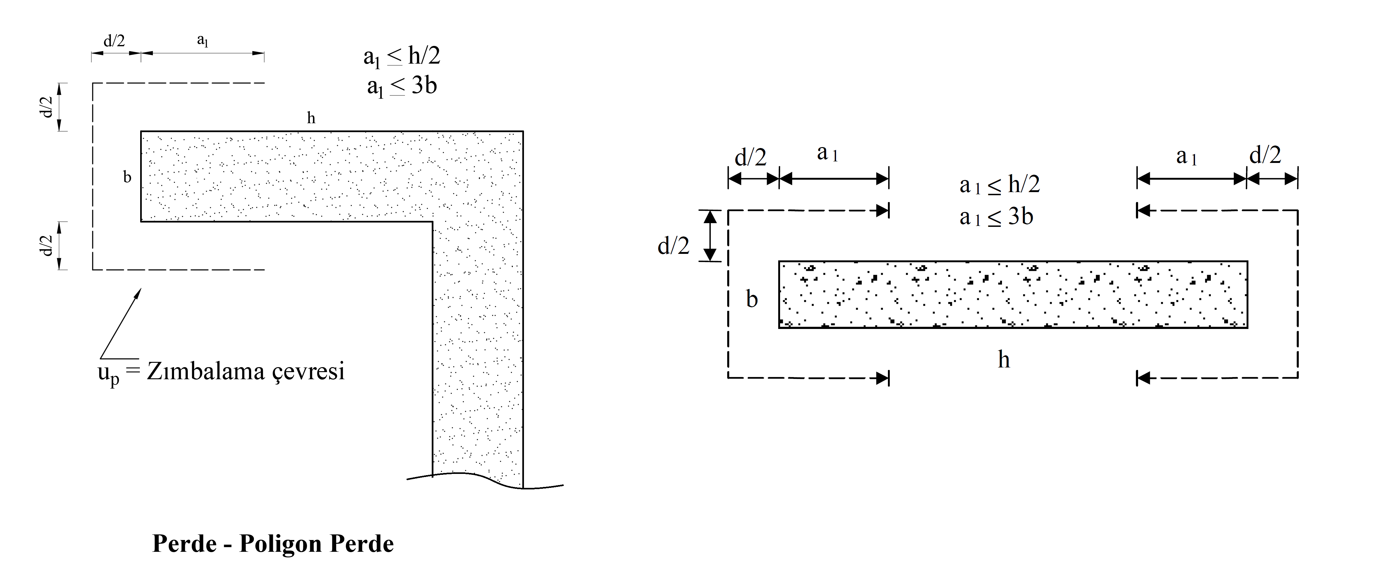
The punching perimeter (u p ) for curtain or group walls is calculated in the curtain end zone in accordance with TS500 Section 8.3.1 . The punching perimeter in the curtain end region is calculated at a distance d / 2 from the outer surface and a distance a 1 from the end of the curtain as shown in the figure below. The lower value is taken into account by comparing the values a 1 distance half the length (h) of the wall or curtain column and three times the wall thickness (b).
In polygon columns, the punching circumference (u p ) is taken into account as shown in the example picture below by creating a suitable geometric shape by drawing tangents at a distance d / 2 from the column surface and corners in accordance with TS500 Section 8.3.1 .
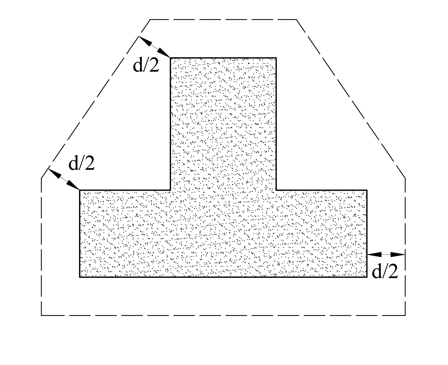
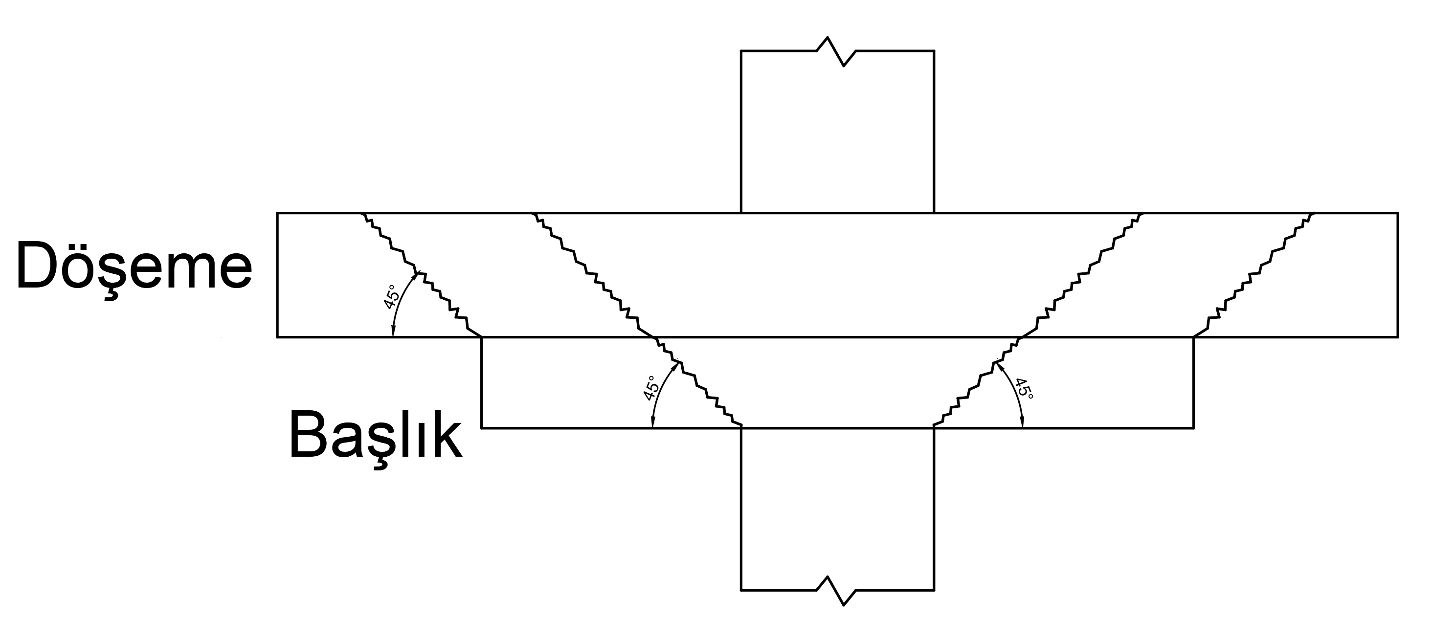
TS500 Section 8.3.1If there is more than one critical section, it is stated that the punching calculation should be made separately for each section. For this reason, when the floor head is defined at the end of the column, there are two separate punching circumference for the column in question and two separate punching calculations are made. In the first case, the punching strength is checked according to the punching circumference calculated at d / 2 distance from the column edges. However, here the slab useful height (d) is obtained by subtracting the cover from the sum of slab thickness and header thickness. In the second case, the punching strength control calculated at a distance of d / 2 from the head edge is checked. In this step, the slab useful height (d) is obtained by subtracting the cover from the slab thickness.
γ: It is the coefficient reflecting the bending effect in the punching calculation. According to TBDY Section 7.11.9 , it is accepted that the value obtained by multiplying the total bending moment transferred from the column in the direction of the earthquake by the coefficient γ with the bending reinforcement and the value obtained by multiplying the coefficient γ v ( v = 1-γ) is assumed to be transferred by punching stresses. . The coefficient of is calculated as shown in TBDY Equation 7.28 .
In this case , the bending moment values (DM d (maj) , DM d (min) ) calculated by considering the Strength Reduction Coefficient D while calculating the punching stresses (τ pd, 1 , τ pd, 2 ) and the coefficient (γ v = 1-γ) multiplied.
c (maj) , c (min) : The center of gravity values in the strong and weak axis direction of the punching area in the moment direction considered.
c ' (maj) , c' (min) : The center of gravity values of the considered moment in the strong and weak axis direction of the reverse punch area.
J (maj) , J (min) : It is the sum of polar inertia and second moments in the strong and weak axes of the surfaces forming the punching area (A z ). J value is calculated by considering the strong axis and weak axis separately. The values of c (maj) , c (min) , c ' (maj) , c' (min) express the distances of the axes taken into account in the calculation of these moments of inertia.
Calculation of J values for a single direction in a sample rectangular column is done as follows. J value is calculated separately on both the strong axis and the weak axis.
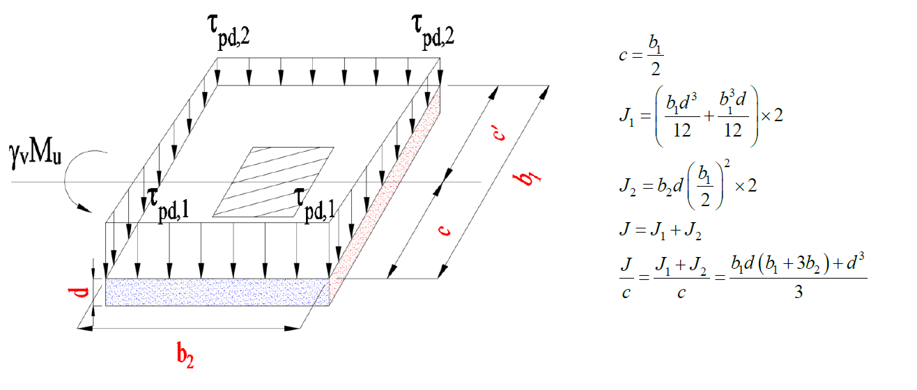
J 1 : It shows the polar moment of inertia of the punching area (red shaded area) perpendicular to the axis in the figure above.
J 2 : The above figure shows the second (inertia) moment of the punching area (blue shaded area) parallel to the axis with respect to the axis.
Use of Stapling Reinforcement
According to Article 7.11.10 of TBDY , in cases whereτ pd ≤ f ctd condition is not fulfilled and plate thickness is greater than 250 mm, punching strength can be increased by using punching equipment.
The punching strength of the reinforcement slab is at most 1.5f ctd , considering the equation specified in TBDY Equation 7.29a , when uniformly spaced wedge or stand reinforcements are used as punching reinforcement .
When shear wedges are used as punching equipment, the punching strength of the reinforcement plate is at most 1.75f ctd considering the equation specified in TBDY Equation 7.29b .
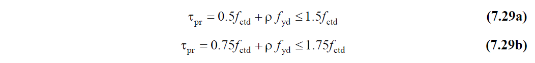
ρ: Cross-sectional area of punching reinforcement per unit area
f yd : Design yield strength of punching reinforcement
In cases where closed stirrup strips in two perpendicular directions are used as punching equipment , the punching strength is at most 1.5f ctd according to TBDY Equation 7.30a .
In cases where two vertical sliding wedge rails are used as punching equipment, the maximum punching strength is 1.75f ctd according to TBDY Equation 7.30b .
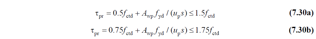
A wp : The total cross-sectional area of the vertical punching rebars on the punching perimeter.
By using punching equipment, the punching strength can be increased up to 1.5f ctd or 1.75f ctd as stated above .
Next Topic