
|
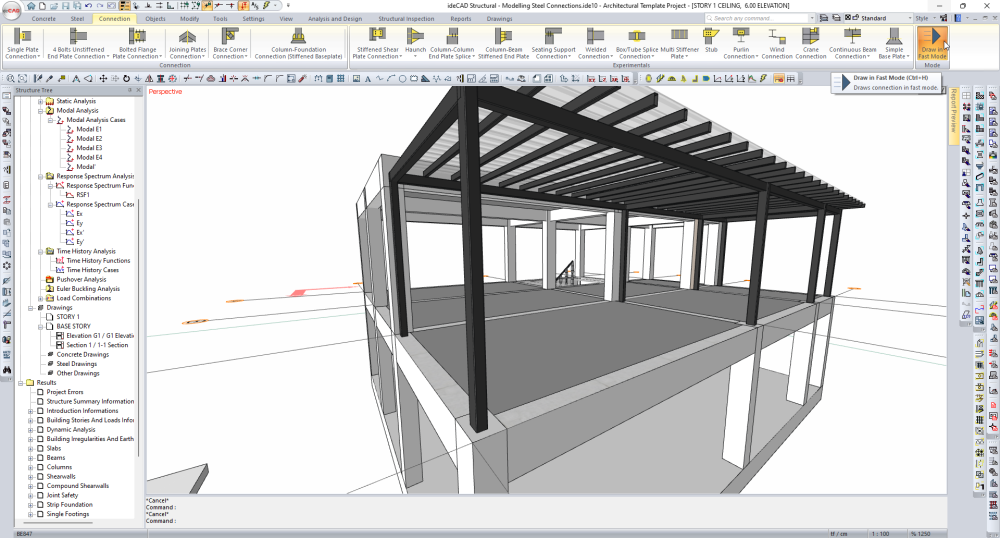
After analyzing the results of the project whose Analysis+Design has been done, steel connections can be modeled. For steel joint modeling, the locations of the elements can be changed accordingly and Analysis+Design is repeated. |
-
Click on the Connection tab under the ribbon menu.
-
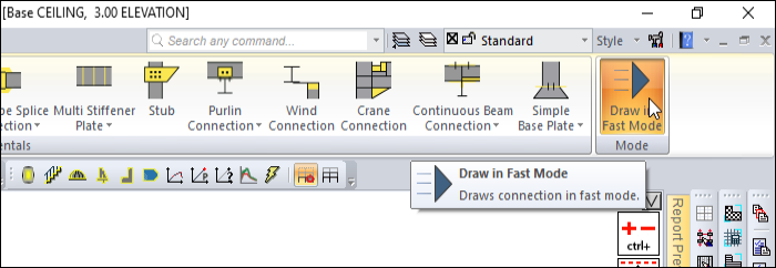
Turn off the draw in fast mode by clicking the Draw in Fast Mode command.
-
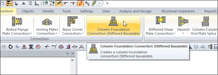
Click the Column-Foundation Connection (Stiffened Baseplate) command.
-
Click on the steel column at the D-1 axis intersection.
-
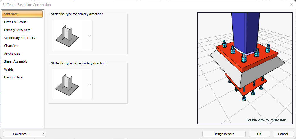
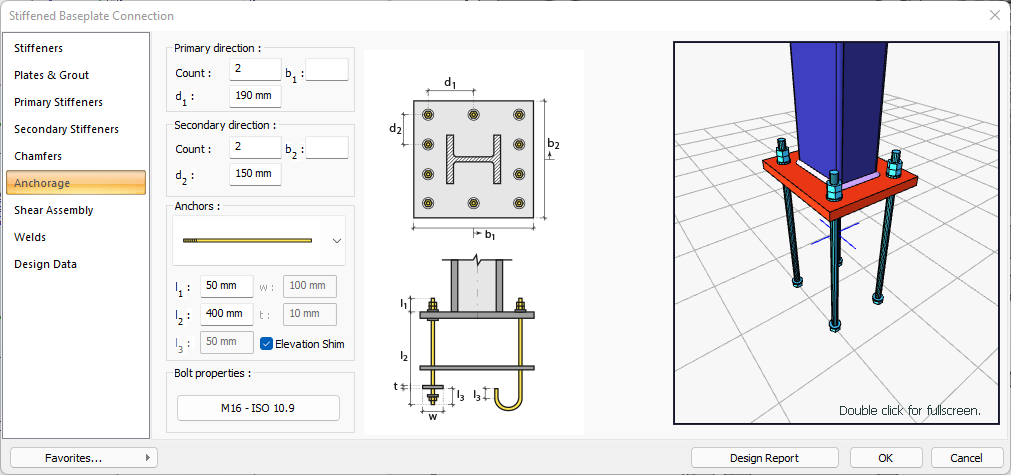
The Stiffened Baseplate Connection dialog will open, that defined to the steel column.
-
Remove the stiffeners plates defined for primary and secondary direction.
-
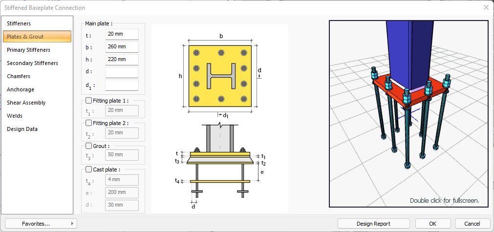
Click the Plates and grout tab.
-
Enter t=20 mm as the plate thickness value under the Main Plate section.
-
Enter the plate dimensions as b=260 mm and h=220 mm.
-
Uncheck the grout option.
-
Uncheck the cast plate option.
-
Click the Anchorage tab.
-
Enter 2 as the primary direction anchor number value.
-
Enter the anchor interval in the primary direction d1=190 mm.
-
Enter 2 as the secondary direction anchor number value.
-
Enter the anchor interval in the secondary direction d2=150 mm.
-
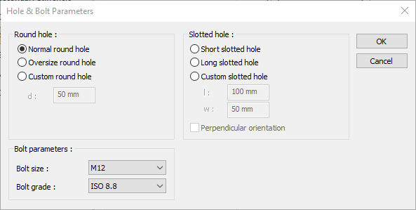
Click the Hole and Bolt Properties button in the Bold Properties section.
-
Select M12 as the bolt size and ISO 8.8 as the bolt grade.
-
Click the OK button to close the dialog.
-
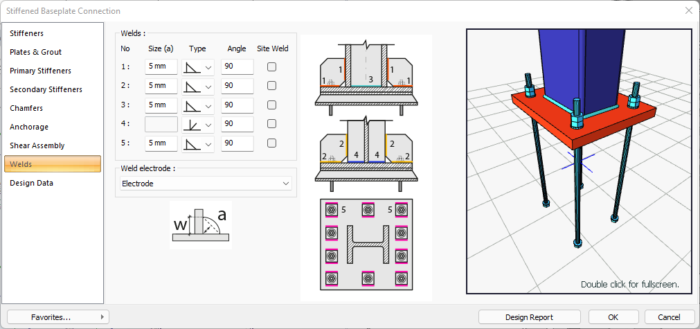
Click on the Welds tab.
-
Enter the values of 5 mm in the weld size lines.
-
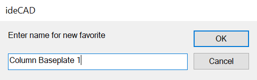
Click on the Add to favorites command the under the Favorites.
-
Give connection to "Column Baseplate 1" name.
-
Click the OK button to close the window.
-
Click the OK button to close the dialog.
-
Activate the Draw in Fast Mode under the Connection tab in the ribbon menu.
-
From the perspective view, click on the steel columns to define the combination named “Column Baseplate 1”.
-
Press the Esc key on the keyboard to exit the command.
-
Turn off the draw in fast mode by clicking the Draw in Fast Mode command.
-
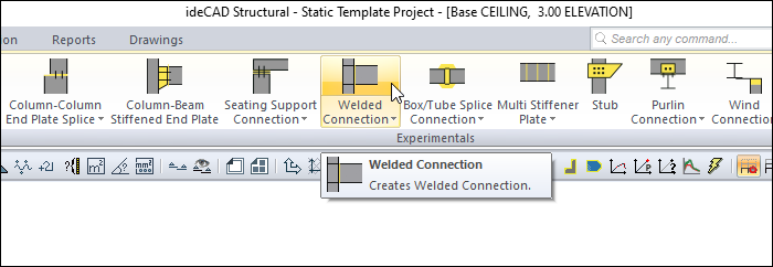
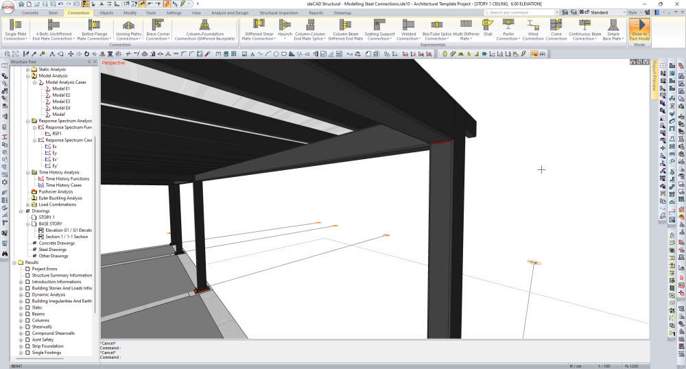
Click the Welded Connection command under the Experimentals heading.
-
It will read 1 in the mouse pointer.
-
Click on the steel column.
-
Click the right mouse button.
-
It will read 2 in the mouse pointer.
-
Click on the steel beam.
-
Click the right mouse button.
-
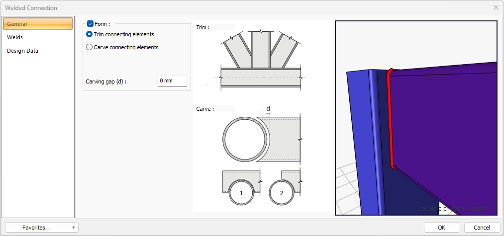
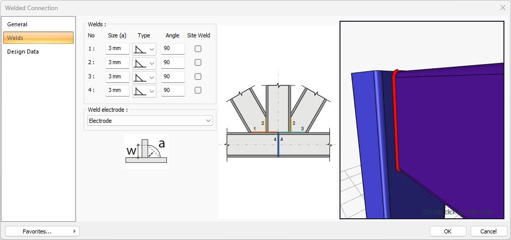
The Welded Connection settings dialog will open.
-
Click on the Welds tab.
-
Enter the size values as 3mm and select the site weld option.
-
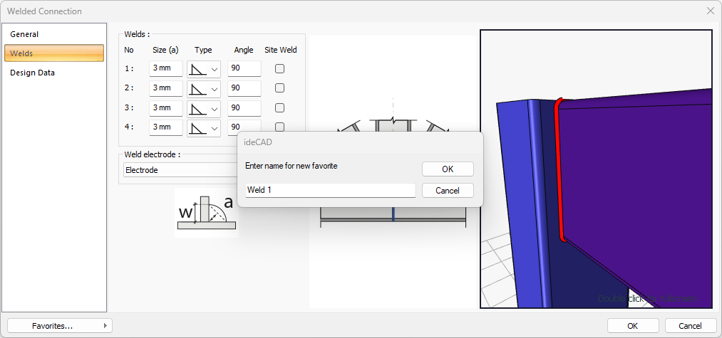
Click on the Add to favorites command the under the Favorites.
-
Give connection to “Weld 1” name and click OK to close the window.
-
Click the OK button to close the dialog.
-
Activate the Draw in Fast Mode under the Connection tab in the ribbon menu.
-
It will read 1 in the mouse pointer.
-
Click on the steel column.
-
Click the right mouse button.
-
It will read 2 in the mouse pointer.
-
Click on the steel beam.
-
Click the right mouse button.
-
Apply similar operations to all column-beam connections.
-
Press the Esc key on the keyboard to exit the command.
-
Click on the Concrete tab.
-
Click the Analysis+Design (F9) command.
-
Do you want to perform analysis? question will be asked.
-
Click the Yes button.
-
Wait for the analysis to complete in the Analysis Status window.
-
After the analysis is complete, click the OK button to close the window.
-
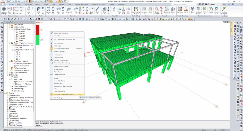
Open the right-click menu in the visualization window .
-
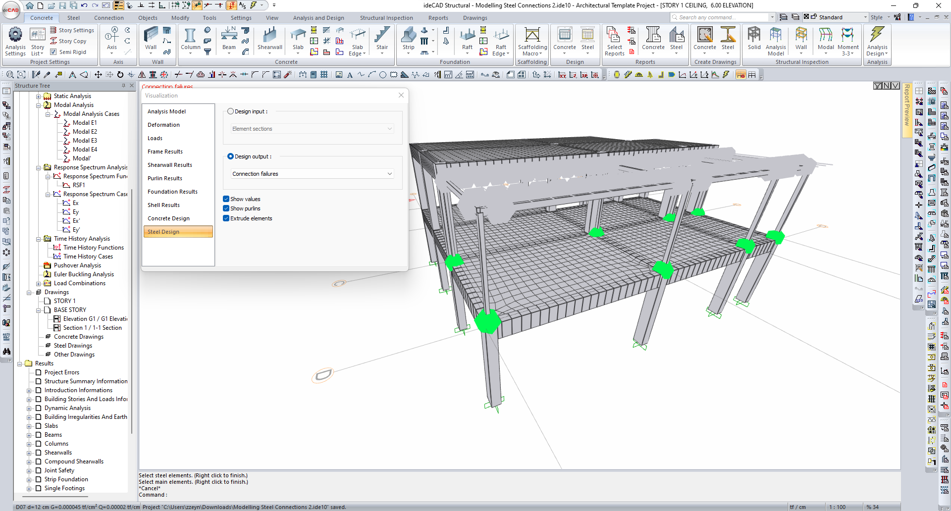
Click on the structural visualization options line.
-
Select Connection Failures from the Steel Design tab Design Output list.
-
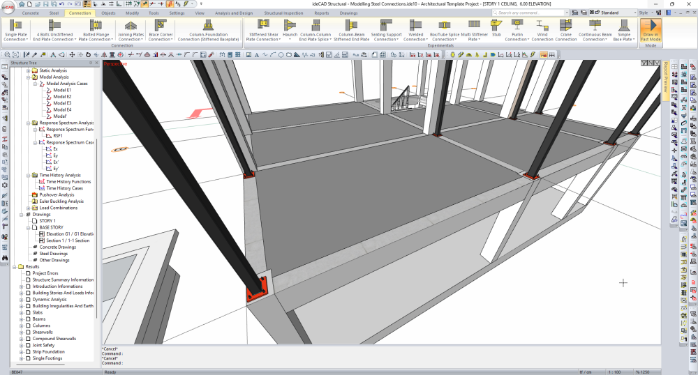
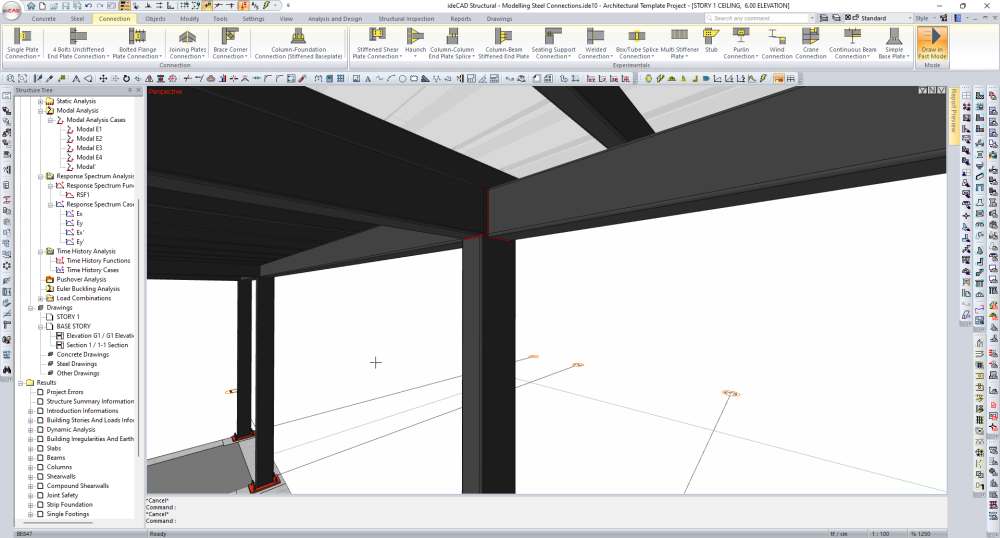
The connection design results will be displayed in the visualization window.
-
Insufficient connections are indicated by red dots and adequate connections by green dots.
|
By downloading the ideCAD Structural BIM Model.ide10 file, you can access the project whose steel connections have been modeled and whose previous steps have been completed together with Analysis+Design. |
Follow the steps of the video below.
Next Tutorial