
In linear performance analysis, the total displaced axis rotation θ k value obtained at the nodal point (end) of each element is used to determine the current structure performance . The displaced axis rotation is obtained using the Mode Combination Method using the rotation value of the node and the relative offset of the element between two nodes.
-
The unit deformation and plastic rotation demands of the element sections are calculated automatically as a result of the Earthquake Calculation with the Mode Combination Method made according to TBDY 4.8.2 .
-
Displaced axis rotation θ k is automatically calculated according to EK 15A .
ICONS
l = Total length of element
l c = Element net span
Δ = Displacementbetween element nodes
θ k = Displaced axis rotation
θ ki = displaced axis rotation at end i
θ kj = displaced axis rotation at end j
θ i = i joint rotation
θ j = j node rotation
The unit deformation and plastic rotation demands of the element sections are obtained as a result of the Earthquake Calculation with the Mode Combination Method made according to Section 4.8.2 of TBDY . As a result of this calculation, the total displaced axis rotation obtained at the node (end) of each element is determined using θ k .
At the end of a bending element i of the pivot axis likelihood disposition θ in Eq. (15A.1) included with.
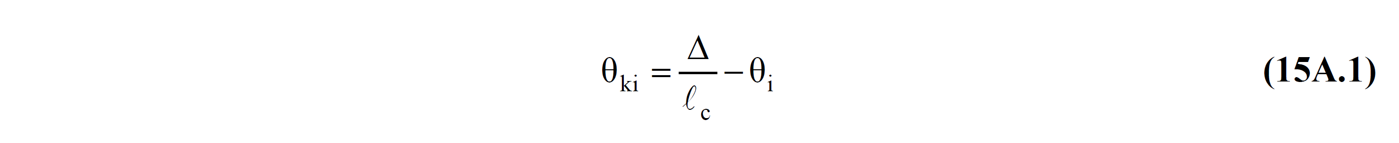
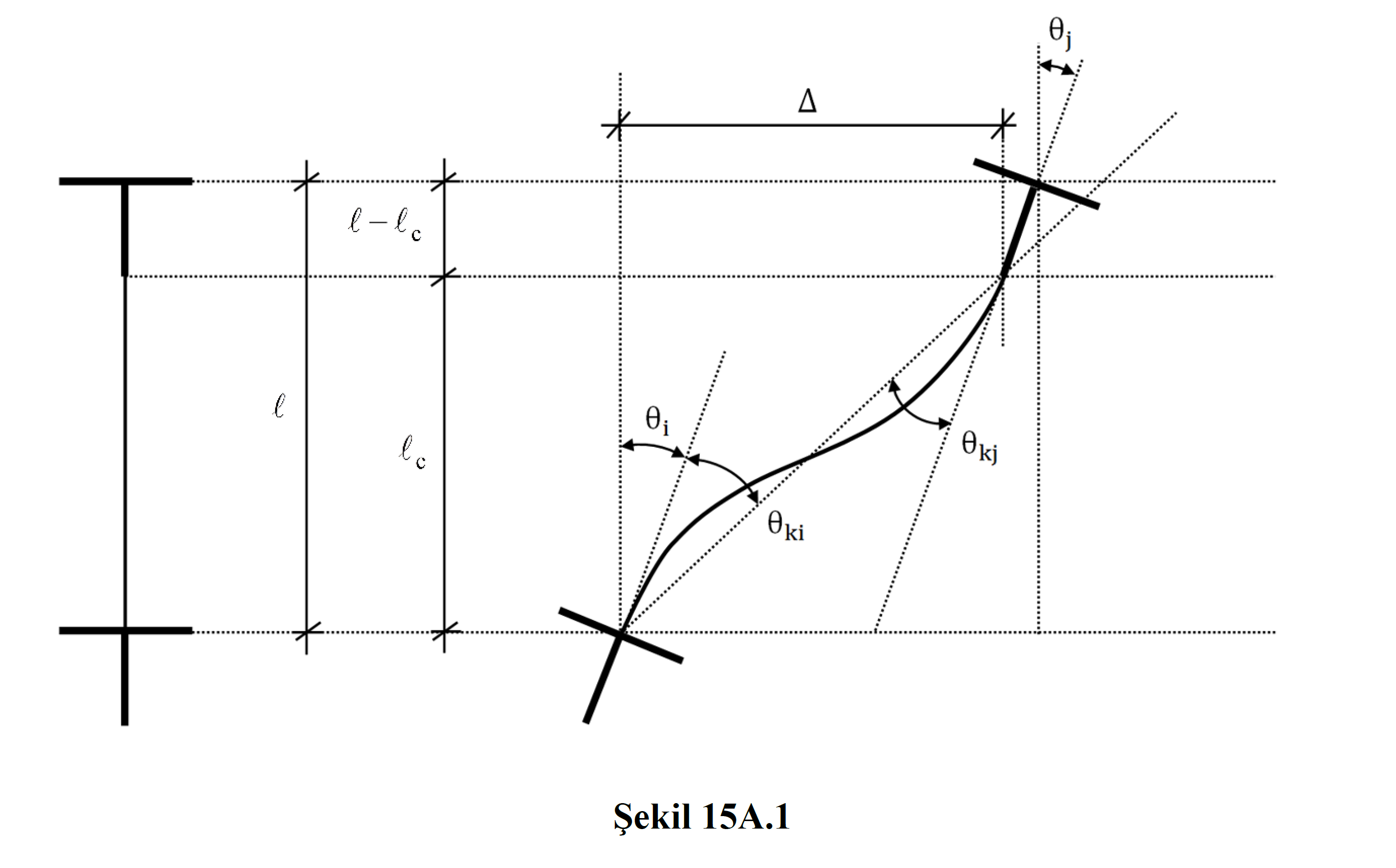
In this equation Δ is the relative displacement (displacement) between two joints, l c means the element net span. θ i is the rotation value of the joint point i obtained as a result of the Earthquake Calculation with the Mode Combination Method . Figure 15A.1 shows the rotation of joint i and j θ i and θ j and displaced axis rotation θ ki and θ kj . The detailed explanation is at Definition of Displaced Axis Rotations for Column, Shearwall and Beam Elements .
Next Topic
Related Topics