
When the Automatic Analysis System Generation command is active, when there are changes made to the elements, newly added elements, etc., the analysis system is created automatically according to these changes.
When the project size grows, the command automatically becomes inactive so that there is no slowness in working.
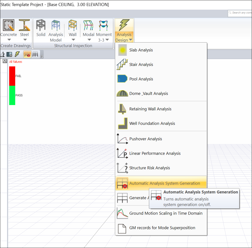
Location of Automatic Analysis System Generation Command
You can access it from the Ribbon menu, Analysis and Design tab , under the Analysis heading .
While analyzing+design is done using the Analysis and Design (F9) command, the program automatically creates the analysis system and then analyzes+designs.
|
Analysis models for various situations are shown in the pictures below. 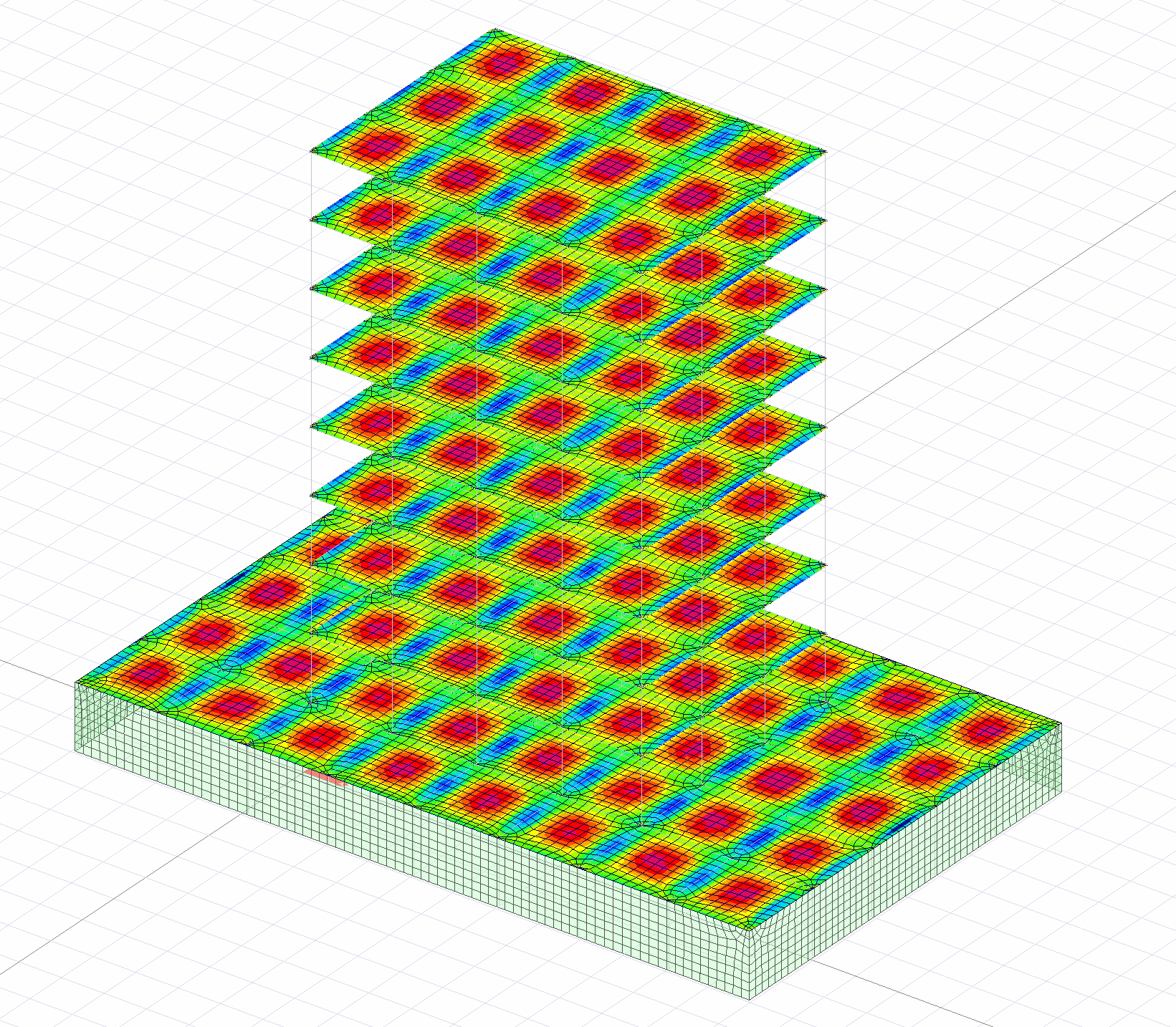
|
|
On the left side of the image below is the solid model image of the elements. In the image in the middle section, the analysis model is created with a semi-rigid diaphragm model and there is a solid-body representation of the rod elements. In the image on the right, there is a bar element representation of the shell column-beams of the slab-walls and the semi-rigid diaphragm model of the analysis model. 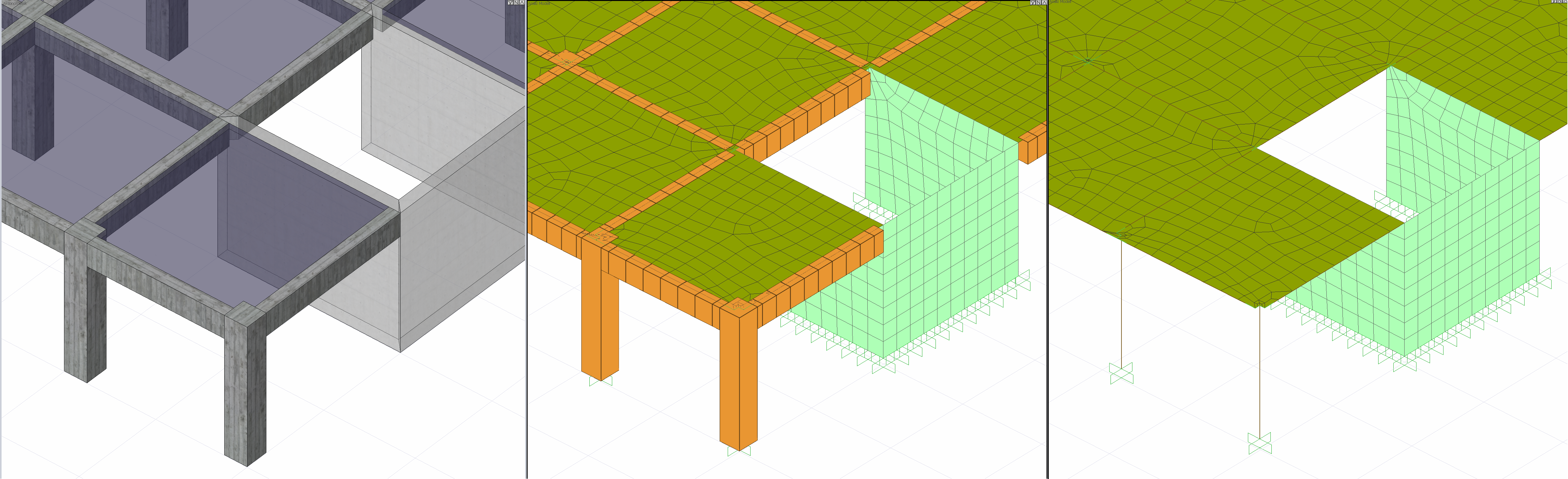
|
|
The following picture shows the analysis model at the connection point of the column-beam elements. The image on the left has a solid model image. The image on the right shows the analysis model created by considering the comma and dimensions in accordance with this solid model. 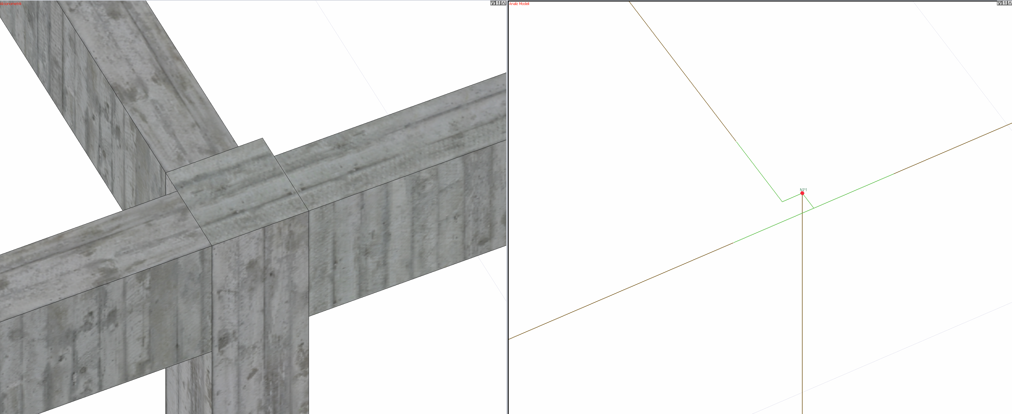
|
Next Topic