
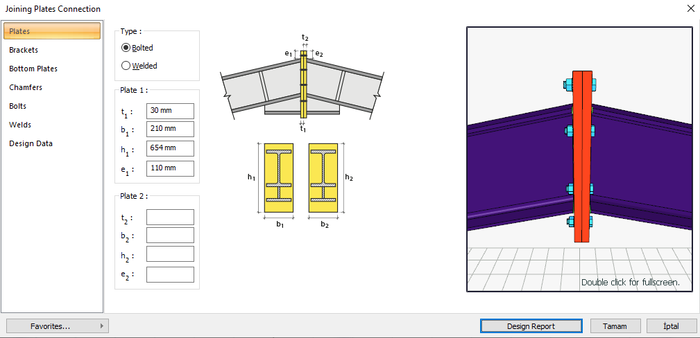
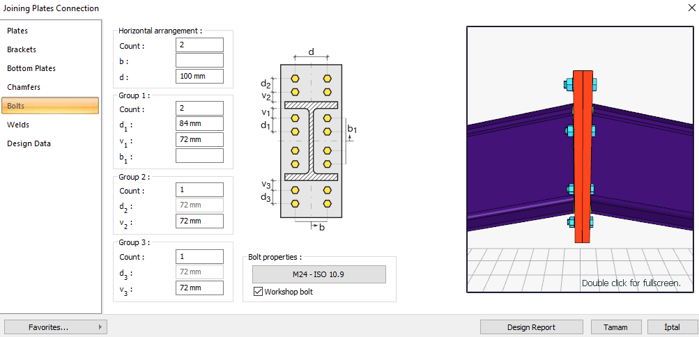
The joining plates connection is a moment transmitting connection formed by connecting the end plates welded to two beams with bolts. Bolt control, welding control, plate control are made automatically according to the placement of the elements of the connection. The connection design of the joining plates connection is made automatically according to the Design, Calculation and Construction Principles of Steel Structures (ÇYTHYEDY) or AISC 360-16 regulations and the connection report is created.
In the calculation of the joining plates connection, the distance between the bolts, the horizontal and vertical edge distance of the bolts and the weld thickness are checked under geometry control. In the strength control, tension in the support bolts, thickness of the end plate, shear yield of the end plate, shear failure of the end plate, slip on the support bolts, crushing of the bolt hole in the end plate and weld strength are checked.
Connection Geometry
Geometry Checks
Horizontal Edge Distance
|
L eh ≥ L e- min |
ÇYTHYEDY 13.3.7 |
|
|
|
L eh |
55 mm |
L eh ≥ 2d = 2 * 24 = 48 mm conformity check for application |
√ |
|
L e- min |
32 mm |
Minimum distance check according to Table 13.9 |
√ |
Vertical Edge Distance
|
L ev ≥ L e- min |
ÇYTHYEDY 13.3.7 |
|
|
|
L ev |
51.515 mm |
L eh ≥ 2d = 2 * 24 = 48 mm conformity check for application |
√ |
|
L e- min |
32 mm |
Minimum distance check according to Table 13.9 |
√ |
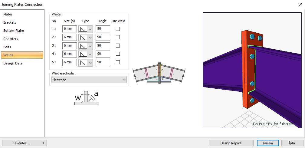
Weld Size 1
|
a ≥ a min |
ÇYTHYEDY 13.3.7 |
|
|
|
a |
6 mm |
|
√ |
|
a min |
3.5 mm |
Table 13.4 |
√ |
Strength Checks
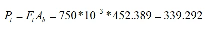
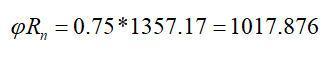
Bolt Tension at Support
|
Ft |
750000 kN/m2 |
|
|
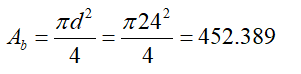
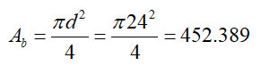
Ab |
|
AISC DG-4-2 nd 3.7 |
|
Pt |
|
|
|
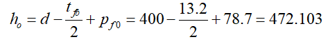
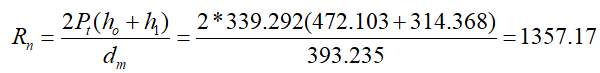
h0 |
|
|
|
x1 |
314.368 mm |
|
|
dm |
393.235 mm |
|
|
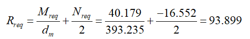
Mreq |
40.179 kNm |
|
|
Nreq |
16,552 kN |
|
|
Rreq |
|
|
|
Rn |
|
|
|
ΦRn |
|
|
|
Required |
Available |
Ratio |
Control |
|---|---|---|---|
|
93.899 kN |
1017.876 kN |
0.092 |
√ |
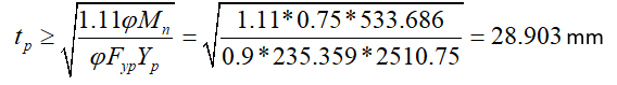
End Plate Thickness
|
A b |
|
|
|
P t |
|
|
|
M n |
|
AISC 358-16 (6.8-5) |
|
F yp |
235346 kN/m2 |
|
|
Y p |
2510.75 mm |
|
|
t p |
|
|
|
Required |
Available |
Ratio |
Control |
|---|---|---|---|
|
28.903 mm |
30 mm |
0.963 |
√ |
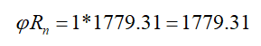
End Plate Shear Yield
|
F yp |
235359 kN/m2 |
|
|
A g |
|
ÇYTHYEDY 13.17 |
|
dm |
393.235 mm |
|
|
M req |
40.179 kNm |
|
|
N req |
16.552 kN |
|
|
R req |
|
|
|
Rn |
|
|
|
ΦRn |
|
|
|
Required |
Available |
Ratio |
Control |
|---|---|---|---|
|
93.899 kN |
1779.31 kN |
0.053 |
√ |
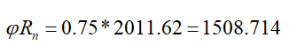
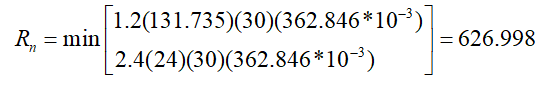
End Plate Shear Rupture
|
F u |
362846 kN/m2 |
|
|
To u |
|
ÇYTHYEDY 13.18 |
|
dm |
393.235 mm |
|
|
M req |
40.179 kNm |
|
|
N req |
16.552 kN |
|
|
R req |
|
|
|
Rn |
|
|
|
ΦRn |
|
|
|
Required |
Available |
Ratio |
Control |
|---|---|---|---|
|
93.899 kN |
1508.714 kN |
0.062 |
√ |
Bolt Shear at Support
|
A b |
|
|
|
Fnv |
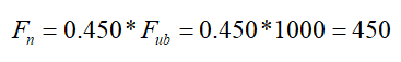
|
|
|
Rn |
|
ÇYTHYEDY 13.10b |
|
ΦRn |
|
|
|
Required |
Available |
Ratio |
Control |
|---|---|---|---|
|
1,058 kN |
610,725 kN |
0.002 |
√ |
Bolt Bearing on End Plate
|
d h |
24+2=26 mm |
|
|
Lc,edge |
|
|
|
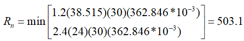
Rn |
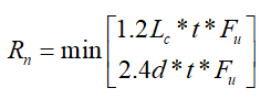
|
ÇYTHYEDY 13.3.13 Equation 13.14a and13.14b |
|
Rn-edge |
|
|
|
Lc,spacing |
|
|
|
Rn-spacing |
|
|
|
Rn |

|
|
|
ΦRn |
|
|
|
Required |
Available |
Ratio |
Control |
|---|---|---|---|
|
1,058 kN |
1695.14 kN |
0.001 |
√ |
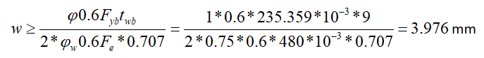
Weld Size 1
|
F yp |
235359 kN/m2 |
AISC DG-4-2 nd 2.1.7 |
|
tbw |
9 mm |
|
|
F e |
480000 kN/m2 |
|
|
in |
|
|
|
Required |
Available |
Ratio |
Control |
|---|---|---|---|
|
3.976 mm |
8.487 mm |
0.469 |
√ |
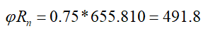
Weld Strength 1
|
in |
8.487 mm |
|
|
F E |
480 N/mm2 |
|
|
the e |
189.75 mm |
|
|
Rn |

|
AISC DG-4-2 nd 2.1.8 |
|
R n / Ω |
|
|
|
Required |
Available |
Ratio |
Control |
|---|---|---|---|
|
1,058 kN |
491.8 kN |
0.002 |
√ |
Next Topic
Related Topics