
Crane Analysis
Crane Classes
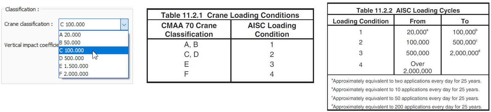
According to AISC Design Guide 07- Industrial Building cranes can be classified based on crane load capacity and depending on the number of cycles it will complete during its lifetime. While A, B, C are light and middle-class cranes, D, E, F are defined as heavy class cranes. These classes are determined according to the load capacity of the crane and the number of times it carries the load during the day, and the cycle it will carry during its lifetime.
Crane Loads
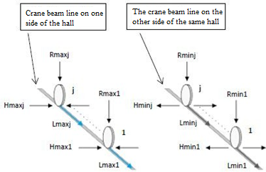
The most unfavourable loading and deflection on cranes are obtained by applying vertical R and horizontal H and L loads on the crane beam in the form of moving load according to the regulation chosen considering the situations such as impact coefficient, effect combinations, loading combinations according to the situation of one or more cranes in the same hall.
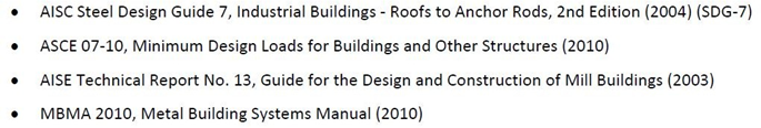
Reference documents used to obtain the effects of cranes on the structural system and unfavourable loading are as follow:
The most unfavourable load for the design of the crane beams is the load that is carried by the crane to rest one direction of the hall. This is the maximum load is used in the crane beam design.
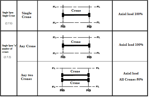
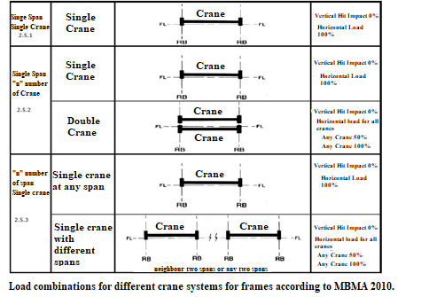
The loads and load ratios to be used in the design of the frame members containing crane are determined according to MBMA 2010 2.5. The AISC SDG-7 clause 13.7 is used to achieve the most unfavourable loading condition in frame design. The minimum effect values are determined for the spans where there is no crane for the frame design.
Crane Beam Design
Combined Effects Control
Biaxial bending control is done in accordance with ÇYTHYEDY 2018. Mx and My are calculated taking into account the impact effect.
Shear Control
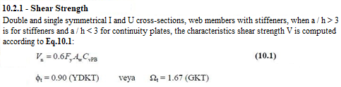
Shear control is made in accordance with ÇYTHYEDY 2018 10.2.1.
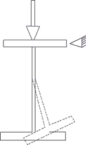
Web Lateral-Buckling Control
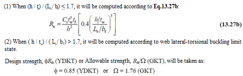
This failure mode may occur due to the crane beam flanges not being braced against rotation and the impact of point loads on the beam due to the crane movement. Point loads with a great magnitude can cause lateral-buckling in the tensile flange and can lead a serious decrease in the strength capacity. In this case, the compression flange reaches the critical buckling stress creating a failure mode. In order to prevent this collapse, the tension flange should be sufficiently rigid and the beam cross-section should be short enough. In the design of the crane beam, attention should be paid to increasing the width of the flange and the thickness of the web in order to increase the cross-section in the most convenient way.
ÇYTHYEDY 2018 13.27b.
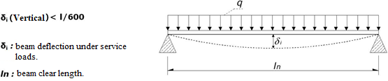
Deflection Control
Made in accordance with AISC Steel Design 7 - Industrial Buildings - Roofs to Anchor Rods 2nd Edition.
Next Topic