
In this Concrete Beam Reinforcement Design example, the bending and shear reinforcement calculations of a 6 m long reinforced concrete beam element are made by independent hand calculation and compared with the results of ideCAD Structural. TS 500 was used in the calculation of the reinforcement area. The beam is under the effect of a uniform load of 36.67 kN / m, one end of which is fixed, and the other is movable support.
|
Compared Value |
Unit |
ideCAD Structural |
Manual solution |
Percentage of error |
|---|---|---|---|---|
|
Md |
kNm |
165.015 |
165.015 |
0% |
|
Ace (bowing) |
mm 2 |
1026 |
1022 |
0.3% |
|
Vd |
kN |
110 |
110 |
0% |
|
VCR |
kN |
93.6 |
93.6 |
0% |
|
Vc |
kN |
74.9 |
74.9 |
0% |
|
Ace (glide) |
mm 2 / mm |
0.1965 |
0.1965 |
0% |
Geometric Properties and System Description
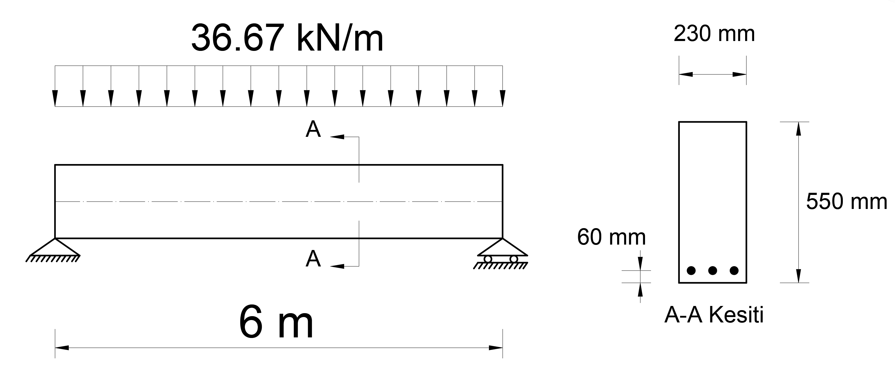
In the picture above, a reinforced concrete beam definition of 55x23 cm is given under the influence of a uniformly distributed load of 36.67 kN / m with a span of 6 m.
Section Properties
h = 550 mm (Section height)
b = 230 mm (Section width)
p p = 60 mm (Cover)
d = 490 mm (Beam useful height, d = hp p )
Material Properties
f ck = 30 MPa (Concrete characteristic compressive strength)
f yk = 420 MPa (Reinforcement characteristic yield strength)
f ctk = 1.917 MPa (Concrete characteristic tensile strength)
Ec = 33000 N / mm 2 (Concrete modulus of elasticity)
Es = 200000 N / mm 2 (Reinforcement steel modulus of elasticity)
υ = 0.2 (Poisson ratio)
You can download the file with the loading status and materials defined below.
TS 500 - Eğilme ve Kayma Donatısı Alanı Hesabı.rar
Required Bending Reinforcement Calculation
Strengths of concrete and reinforcement steel should be used as follows for bearing capacity limit state according to TS 500 Article 6.2.5 . These values will also be used for the required flexural reinforcement area A s .
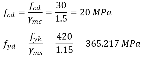
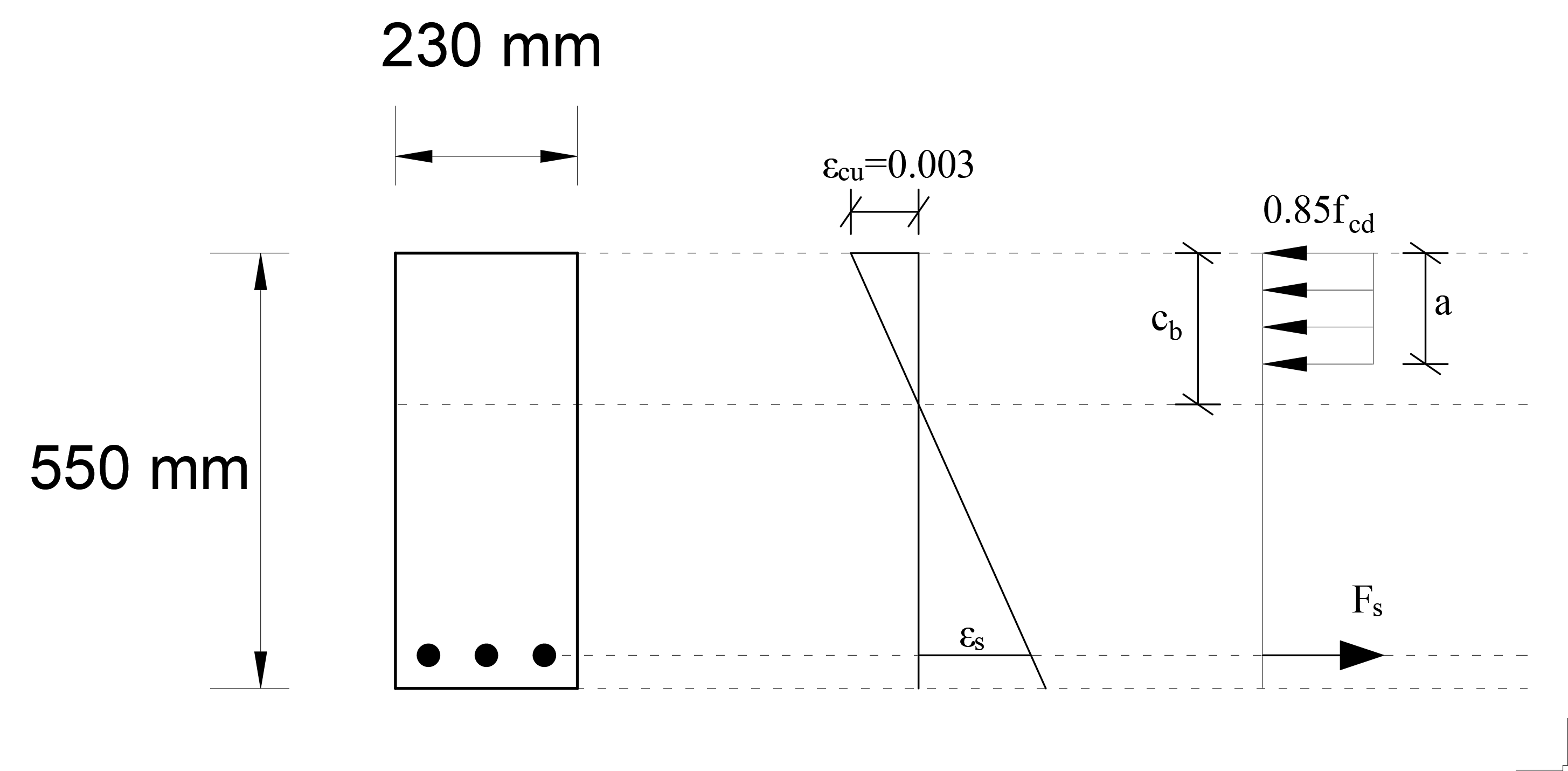
In these relations, the design compressive strength of concrete is given as f cd , and the design yield strength of reinforcement steel is given as f yd . γ mc and γ ms are the material coefficients for concrete and reinforcing steel, respectively. Equivalent rectangular pressure block will be used for ease of calculation. Equivalent pressure intensity of 0.85f cd is used as block width . In this case, the unit strain and stress distribution under the bending effect of the reinforced concrete section can be shown as follows.
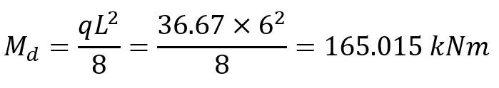
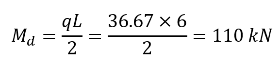
The design moment M d value under uniformly distributed load is found as follows.
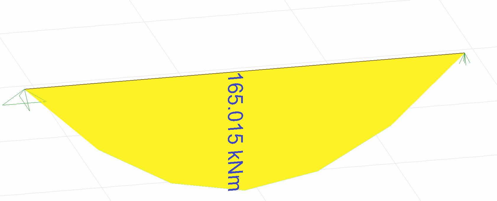
The design moment M d must be equal to the total moment of the stress distribution shown above. Since the reinforcement area A s is the unknown value, the concrete pressure block depth a can be calculated by taking the moment according to the position of the reinforcement, a by the solution of the following equation.
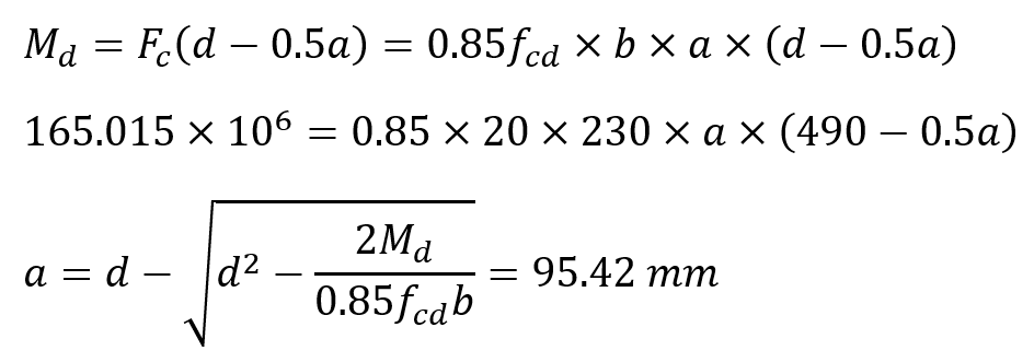
Note: Since the above equation M d = 0.85f cd * b * a * (d-0.5a) is a quadratic equation with one unknowns, there are two "a" values. However, one of them is meaningless. Therefore, the value 95.42 should be taken into consideration.
Concrete pressure block depth was found as a = 95.42 mm. In this case, the required reinforcement area A s can be found by establishing the horizontal equilibrium equation .
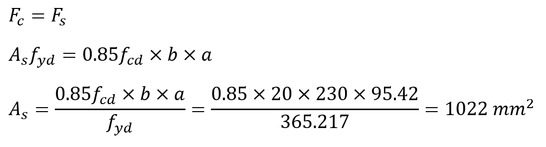
In this case, the area of reinforcement flexural reinforcement required for the moment of M d = 165.015 kNm was found to be A s = 1022 mm 2 .
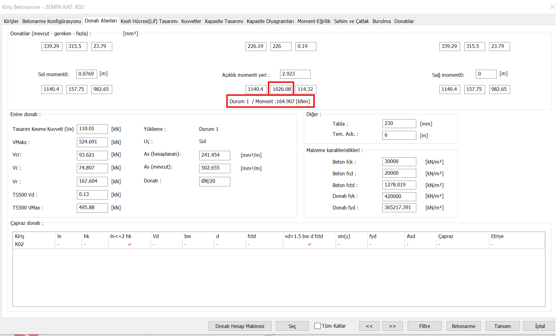
The area of reinforcement flexural reinforcement required for the moment of M d = 165.015 kNm A s = 1022 mm 2 value ideCAD Structural results are very close to As = 1026 mm 2 .
Required Shear Reinforcement Calculation
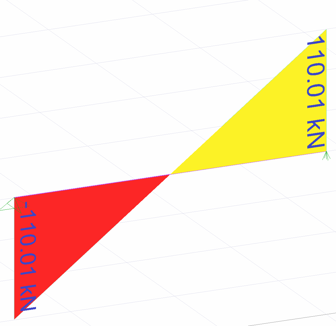
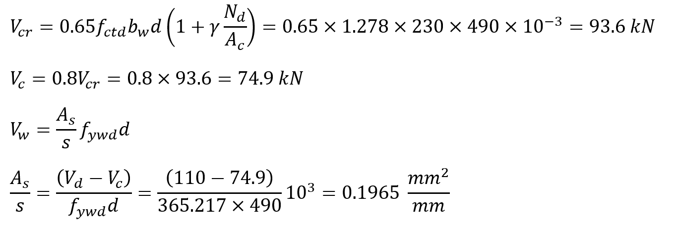
The shear force under uniform load effect is found as follows. The largest value of this shear diagram is the required shear strength V d value.
In TS 500 8.5.1.2 , the largest shear force limit is calculated as follows.
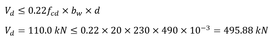
Cutting force upper condition is provided.
The required shear strength is calculated according to V r TS 500 as follows.
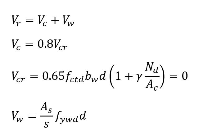
The unknown value in these equations is the value of shear reinforcement area A s . The required shear strength was found as V r = 110 kN. In this case, the reinforcement area A s required for the shear force is calculated as follows.
According to TS 500 Article 8.1.5.1 , minimum shear reinforcement area is calculated as follows.
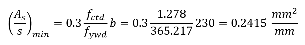
In this case, the value of shear reinforcement area A s is determined as 0.2415 mm 2 / mm according to the minimum value .
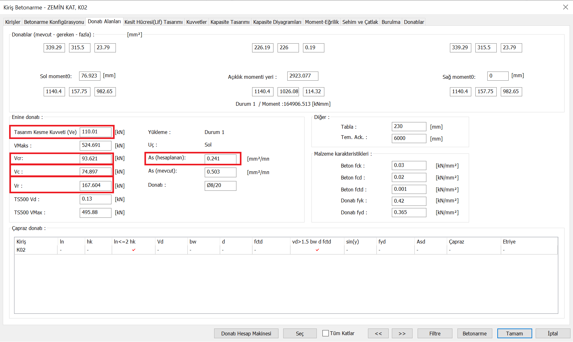
As can be seen, the results of V d = 110 kN, V cr = 93.6 kN, V c = 74.9 kN, A s = 0.2415 mm 2 / mm were found to be the same with ideCAD Structural.
Next Topic