
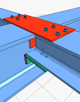
With the Continuous Beam Connection command, beam-beam connection is defined. It can be applied to one piece main beam and two piece beam connections.
Location of the Continuous Beam Connection Command
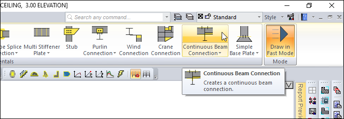
You can access it under the Ribbon menu, Connection tab, Experimentals title.
Usage Steps
-
From the Steel menu click on the line Continuous Beam Combination.
-
Click the main beam, then the beam, in the 3D perspective view.
-
The combination will occur with default settings.
Location of the Continuous Beam Connection Settings Dialog
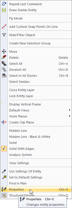
Select the connection and click the right mouse button. Click the Properties line from the right click menu that opens.
Continuous Beam Connection Settings Dialog
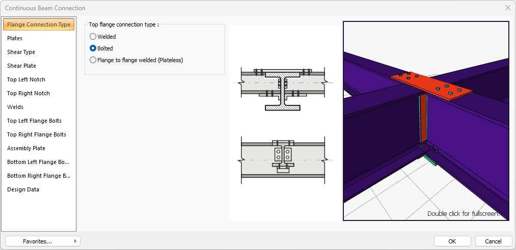
Flange Connection Type
|
Specifications |
|---|
|
Top flange connection type 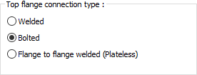
Connection type is selected for the top header. |
|
Schematic drawing 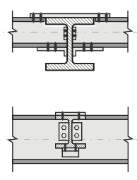
Connection and placement values are shown on the schematic drawing. |
|
Preview 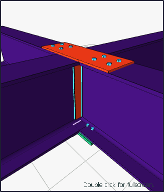
There is a preview of the connection. The selection made and the entered values can be followed simultaneously in the preview. |
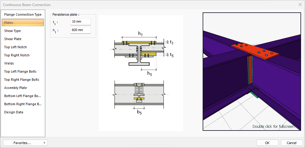
Plates Tab
|
Specifications |
|---|
|
Persistence plate 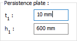
Persistance plate is determined by entering the value. The values to be entered are shown in the schematic drawing. |
|
Schematic drawing 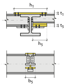
Connection and plate values are shown on the schematic drawing. |
|
Preview
There is a preview of the connection. The selection made and the entered values can be followed simultaneously in the preview. |
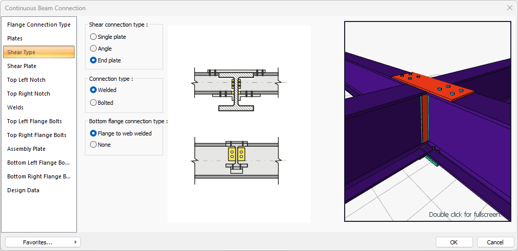
Shear Type Tab
|
Specifications |
|---|
|
Shear connection type 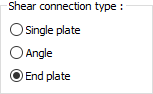
The shear connection type is selected. |
|
Connection type 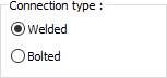
Welded or bolted connection types are selected. |
|
Bottom flange connection type 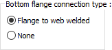
Connection type is selected for the bottom flange. |
|
Schematic drawing 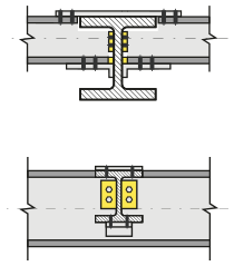
Connection and plate values are shown on the schematic drawing. |
|
Preview
There is a preview of the connection. The selection made and the entered values can be followed simultaneously in the preview. |
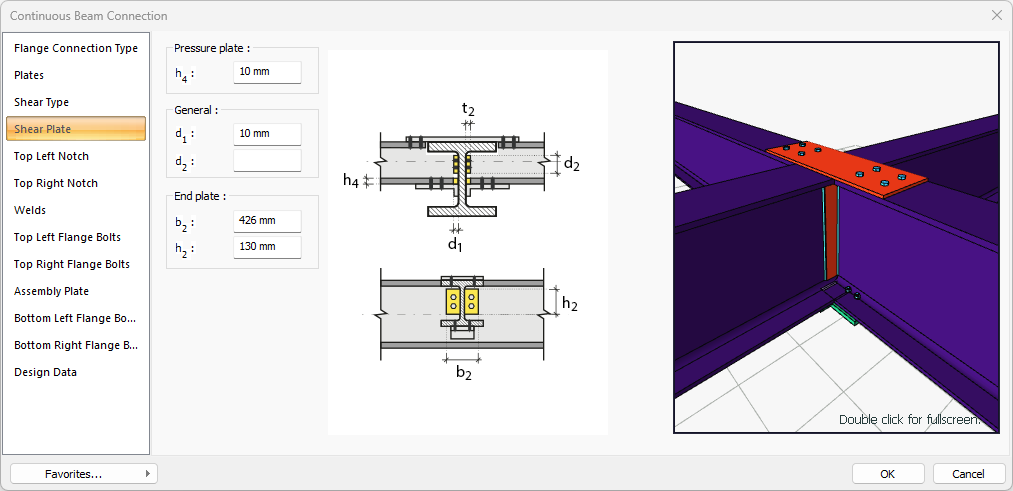
Shear Plate Tab
|
Specifications |
|---|
|
Pressure plate The pressure plate is determined by entering the value. The values to be entered are shown in the schematic drawing. |
|
General 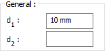
The value is entered to determine the location of the plate according to the beam section. The values to be entered are shown in the schematic drawing. |
|
End plate 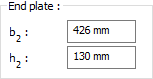
The end plate is determined by entering the value. The values to be entered are shown in the schematic drawing. |
|
Schematic drawing 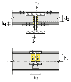
Connection and plate values are shown on the schematic drawing. |
|
Preview
There is a preview of the connection. The selection made and the entered values can be followed simultaneously in the preview. |
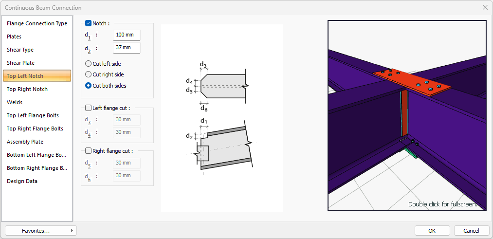
Top Left/Top Right Notch Tab
|
Specifications |
|---|
|
Notch 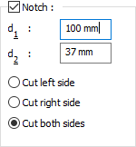
If the option is selected, notch is done according to the entered values. The values to be entered are shown in the schematic drawing. |
|
Left flange cut 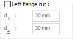
If the option is selected, left flange cutting is made according to the entered values. The values to be entered are shown in the schematic drawing. |
|
Right flange cut 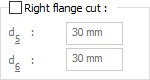
If the option is selected, right flange cutting is made according to the entered values. The values to be entered are shown in the schematic drawing. |
|
Schematic drawing 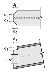
Connection, notching and cutting values are shown on the schematic drawing. |
|
Preview
There is a preview of the connection. The selection made and the entered values can be followed simultaneously in the preview. |
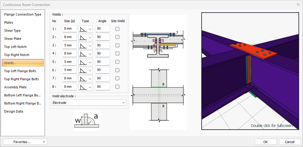
Welds Tab
|
Specifications |
|---|
|
Welds 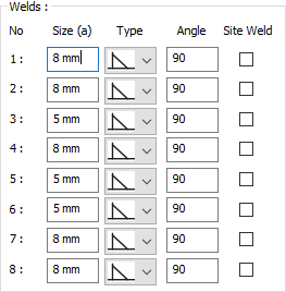
The thickness, type and angle values of the welds to be made at the connections are given. The information on whether it will be done on the construction site or not is entered. |
|
Weld electrode The strengths of the welding electrodes are defined in the design inputs. The strength of the main element in the weld joint is controlled under the condition that it has less strength than the weld strength. If necessary, click the list and define "Create New…". To create the welding electrode, give the information "Name" and "Weld metal tensile strength" in the dialog that opens after clicking "Create New". Welding geometry is determined automatically by the program. These properties can be changed to easily determine the connection properties. Geometry features are in accordance with industry standards and in the form specified in AISC. |
|
Schematic drawing 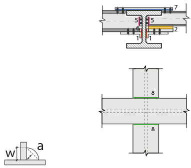
Connection and weld values are shown on the schematic drawing. |
|
Preview
There is a preview of the connection. The selection made and the entered values can be followed simultaneously in the preview. |
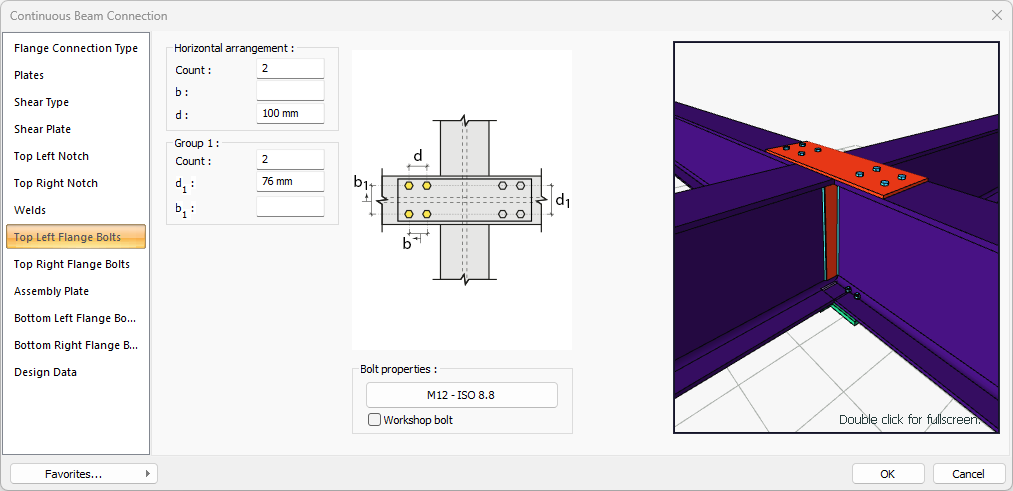
Top Left Flange Bolts Tab
|
Specifications |
|---|
|
Horizontal arrangement 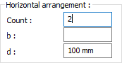
The horizontal arrangement distance value of the bolts is entered. The values to be entered are shown in the schematic drawing. |
|
Group 1 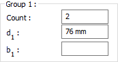
Distance values of bolts to beam and other bolts are entered. The values to be entered are shown in the schematic drawing. |
|
Bolt properties 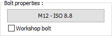
The Hole and Bolt Parameters dialog is opened by clicking on the bolt properties button. The bolt properties are set in this dialog. |
|
Schematic drawing 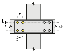
Connection and bolt arrangement values are shown on the schematic drawing. |
|
Preview
There is a preview of the connection. The selection made and the entered values can be followed simultaneously in the preview. |
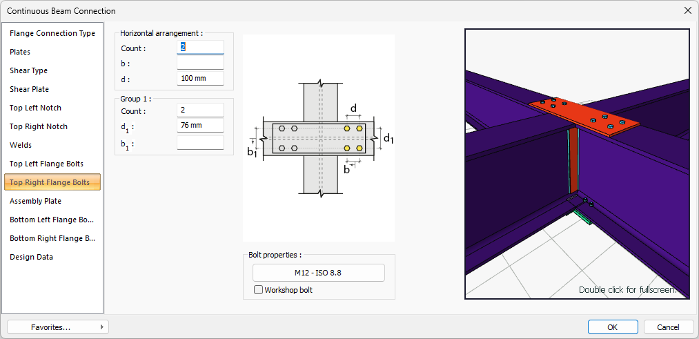
Top Right Flange Bolts Tab
|
Specifications |
|---|
|
Horizontal arrangement
The horizontal arrangement distance value of the bolts is entered. The values to be entered are shown in the schematic drawing. |
|
Group 1
Distance values of bolts to beam and other bolts are entered. The values to be entered are shown in the schematic drawing. |
|
Bolt properties
The Hole and Bolt Parameters dialog is opened by clicking on the bolt properties button. The bolt properties are set in this dialog. |
|
Schematic drawing 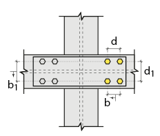
Connection and bolt placement values are shown on the schematic drawing. |
|
Preview
There is a preview of the connection. The selection made and the entered values can be followed simultaneously in the preview. |
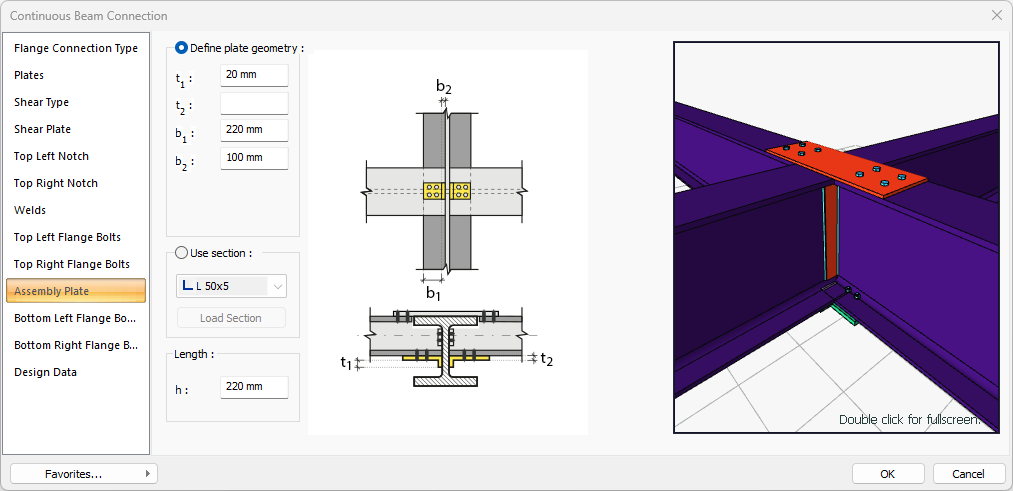
Assembly Plate Tab
|
Specifications |
|---|
|
Define plate geometry 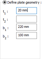
If the option is selected, the assembly plate is determined by entering the values. The values to be entered are shown in the schematic drawing. |
|
Use section 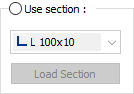
By selecting the option, one of the ready-made L profiles is selected from the list as an assembly plate. By clicking on the Load section button, you can reach the ready section library and reach the list of American and European finished rolling sections and select from the list. |
|
Length 
The assemblyplate length to be used is determined by entering the value. |
|
Schematic drawing 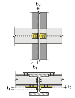
Connection and plate values are shown on the schematic drawing. |
|
Preview
There is a preview of the connection. The selection made and the entered values can be followed simultaneously in the preview. |
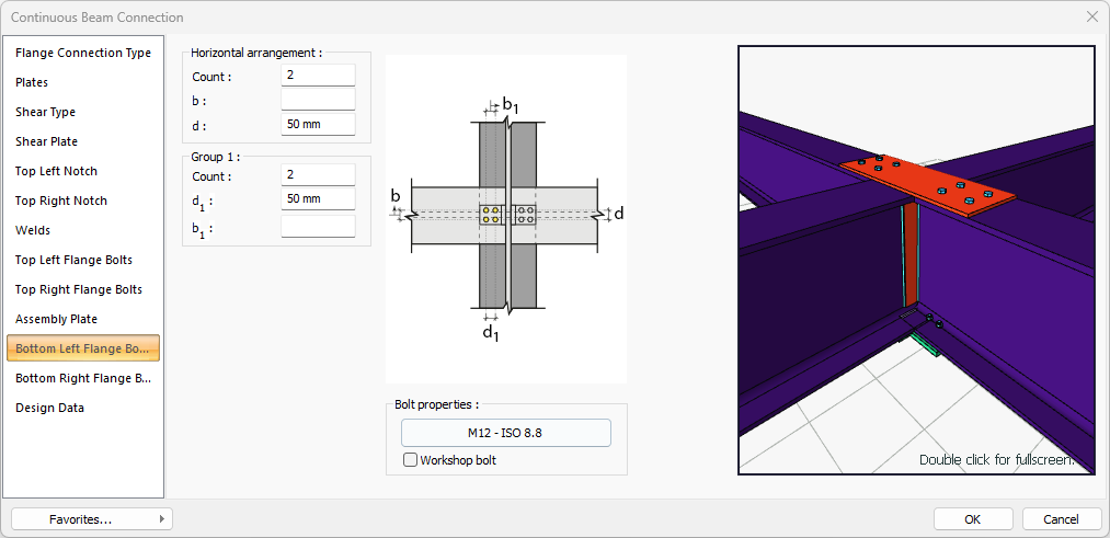
Bottom Left Flange Bolts Tab
|
Specifications |
|---|
|
Horizontal arrangement 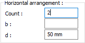
The horizontal arrangement distance value of the bolts is entered. The values to be entered are shown in the schematic drawing. |
|
Group 1 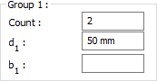
Distance values of bolts to beam and other bolts are entered. The values to be entered are shown in the schematic drawing. |
|
Bolt properties
The Hole and Bolt Parameters dialog is opened by clicking on the bolt properties button. The bolt properties are set in this dialog. |
|
Schematic drawing 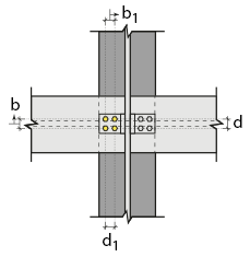
Connection and bolt arrangement values are shown on the schematic drawing. |
|
Preview
There is a preview of the connection. The selection made and the entered values can be followed simultaneously in the preview. |
Bottom Right Flange Bolts Tab

|
Specifications |
|---|
|
Horizontal arrangement
The horizontal arrangement distance value of the bolts is entered. The values to be entered are shown in the schematic drawing. |
|
Group 1
Distance values of bolts to beam and other bolts are entered. The values to be entered are shown in the schematic drawing. |
|
Bolt properties
The Hole and Bolt Parameters dialog is opened by clicking on the bolt properties button. The bolt properties are set in this dialog. |
|
Schematic drawing 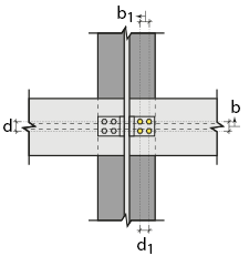
Connection and bolt arrangement values are shown on the schematic drawing. |
|
Preview 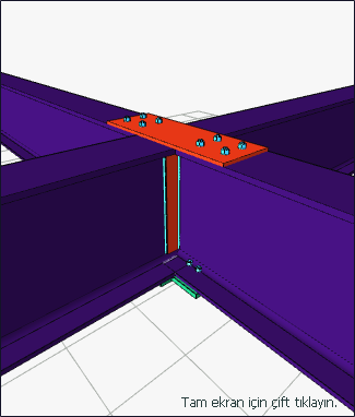
There is a preview of the connection. The selection made and the entered values can be followed simultaneously in the preview. |
Design Data Tab
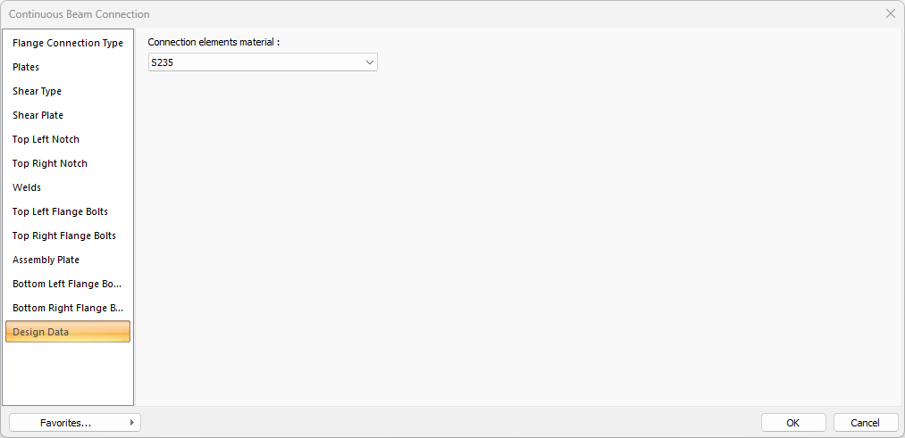
In the design data, the connection elements material is defined. The condition that the main element in the weld joint has less strength than the weld strength is controlled.
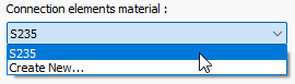
If necessary, click the list and define "Create New…". To create the connection elements material, give the information material definitions and values in the dialog that opens after clicking "Create New".