
The elements defined for frame / wing records are called profiles. In the picture below, the areas created by the profile are colored green in the plan and facade view.
In the picture below, there is a close-up view of the upper part of the case to show the effect of the profile.
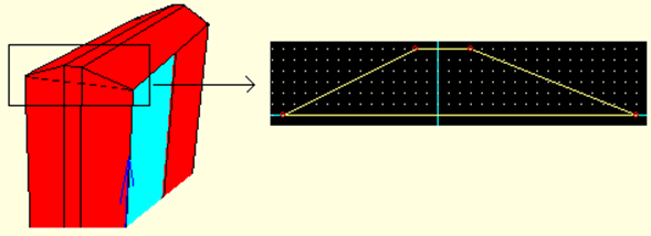
Profile Editor
When you click on the Construction / Profile Editor line, you will see the profile editor. With this editor, you can make changes on profiles or create new profiles.
Latest Status Section:
While moving a joint point, you can enter values in terms of m in the X and Y values section and click the Apply button to place the node according to the origin point with the values you entered.
Zoom Section:
Enlarge: By clicking the enlarge button and clicking on the drawing window, the point to be taken into account while zooming can be specified. By clicking the enlarge button, it will be zoomed in consideration of the center of the screen.
Zoom Out : By clicking on the Shrink button, it will be zoomed in consideration of the center of the screen.
Boundaries: It will be zoomed in consideration of the boundaries of the selected profile.
To Add a Node
If you click on one of the lines twice, the line will be split in half and a joint will be created.
To Delete a Node
When you hold one of the node points and place it on another, the first point will be deleted as these two points will join.
Not
In order for the superimposed nodes to merge, there should not be any other point between the two points.
A profile cannot be less than 3 points.
To Cancel Case Edges
You can cancel the frame edges by making a single line profile.
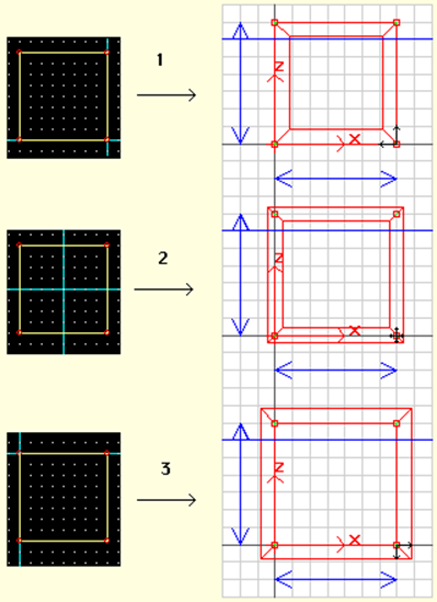
The Effect of the Profile's Origin Point on the Safe
The effect of the profile origin point on the frame will occur at the frame borders. For example;
-
If the origin point of the profile is defined as one of the lower corners, the frame edges will extend inward from the nodes. It will ensure that the window has the desired dimensions. It can be seen in example number 1.
-
If the origin point of the profile is defined as the midpoint, the frame edges will extend from the nodes half in and half out. It can be seen in example number 2.
-
If the origin point of the profile is defined as one of the upper corners, the frame edges will extend outward from the nodes. It will cause the frame to be as big as the Y-axis of the profile from the specified dimensions. It can be seen in example number 3.
From the examples given, it will be easier to dimension the sample design number 1. In the applications in other examples, the nodes should be adjusted again or the design settings should be checked.
Defining a Profile and Assigning it to a Safe
Defining the Profile
Let's define a profile with a width of 5 cm and a thickness of 6 cm for frame and sash records.
-
Click on the Construction / Profile Editor row.
-
Enter 0.01 for the X / Y values in the grid section. These values represent the distances of the jump points on the grid.
-
Click the New button in the lower right corner . Enter a name for the profile you want to create. You will see a profile of x = 6 cm y = 6 cm.
-
In the grid section, check the Lock to grid option, so you will be able to resize as whole numbers.
-
Changes you make in the Y axis in the profile will be reflected in the width of the frame edges and the thickness of the changes you make in the X axis.
-
The designed case edge thickness will be 6 cm and the width will be 5 cm. In this case, the frame can be created as designed by shortening the height of the profile by 1 cm and obtaining a profile with the dimensions x = 6, y = 5 cm. To do this, click the point in the upper right corner and move it to a lower point in the grid. Do the same with the dot in the upper left corner.
-
We need to move the origin point of this profile to the lower right corner in order to ensure that the frame edges extend from the nodes and form within the design boundaries.
-
Click the Set origin point icon.
-
Click the bottom right node of the profile
-
Click the OK button. Against your Changed Under Profile for whether to register? message will come. Click on the Yes button.
Assigning Profile to Vault
-
Click the Properties line from the list that opens when you point to the safe and click the right mouse button .
-
The Case / Wing dialog will be displayed. Select the name of the profile you created from the Profile row in the parameters section in the middle .
-
When you click the OK button, the profile you selected will be assigned to the safe.
Case Examples Based on Selected Profile
Vault images will change according to the selected profiles.
Next Topic