
In this example, Dead loads are increased, so that the bending moment value of the element is greater than the cracking moment value of the element.
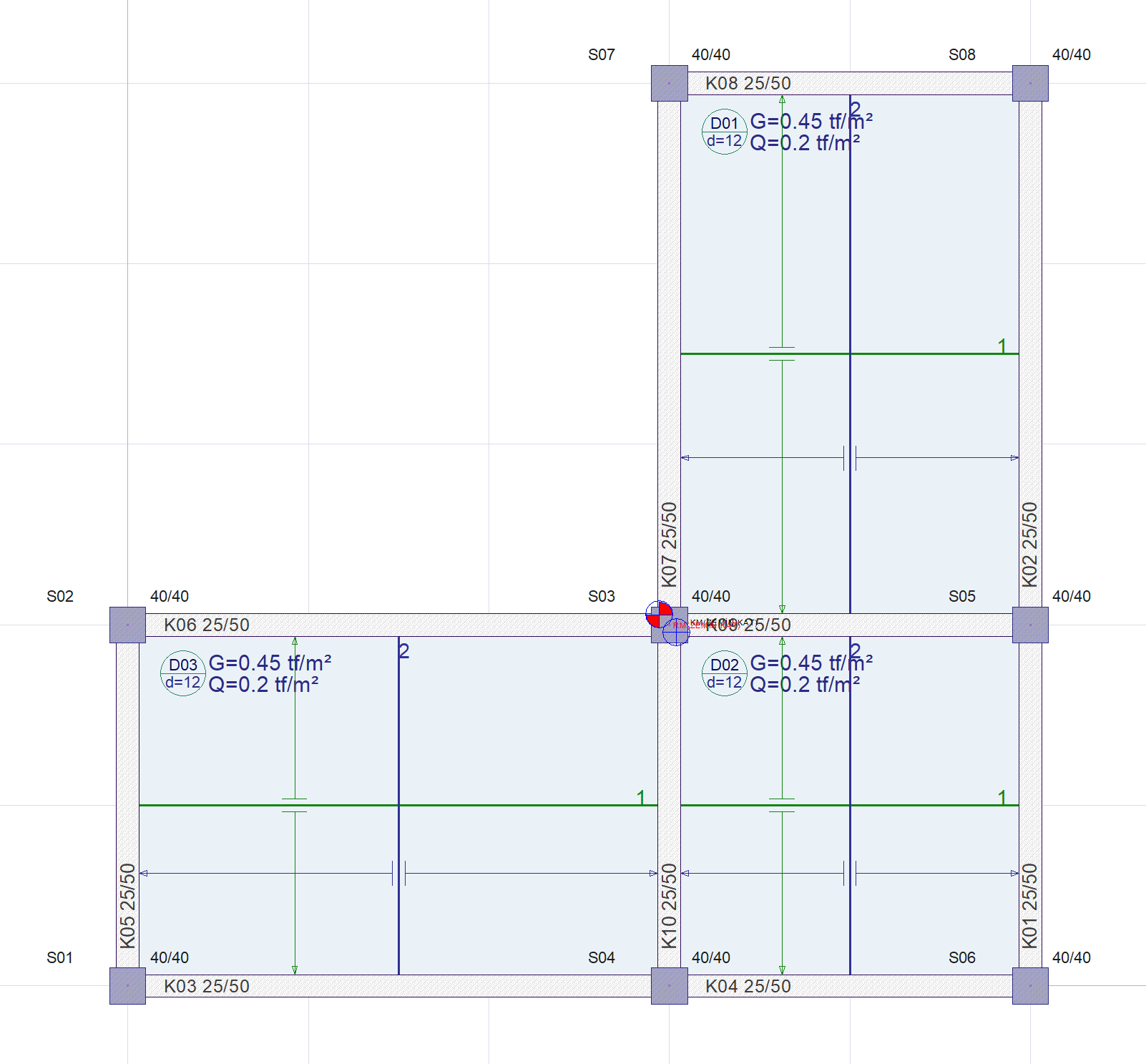
In the structure whose plan view is given in the image below, the instantaneous deflection calculation will be made for the K06 beam and compared with the ideCAD results. For the K06 beam, instantaneous deflection under the effect of live loads (Q) and instantaneous deflection and time-dependent deflection calculations for Dead Loads (G) will be made. The results will be compared with ideCAD v10 by calculating the total deflection from the deflections consisting of fixed and live loads.
Important Note: Deflection in reinforced concrete elements is calculated with Effective Moments of Inertia in ideCAD software . Then, taking into account these effective moments of inertia, a new analysis is made for the deflection control of the structure only. However, in this example, approximate formulas will be used to calculate the beam deflection calculation easier by hand and only deformations due to bending will be considered. In ideCAD software, the deformation effects of all internal forces are taken into account. For this reason, manual calculation and ideCAD results may differ slightly.
Proje Dosyası
Instantaneous and Time Dependent Deflection Example 2.rar
K06 Beam Section Properties
-
Modulus of elasticity of concrete, Ec = 30250 MPa
-
Modulus of elasticity of Reinforcement Es = 200000 MPa
-
Design tensile strength of concrete, fctd = 1.167 MPa
-
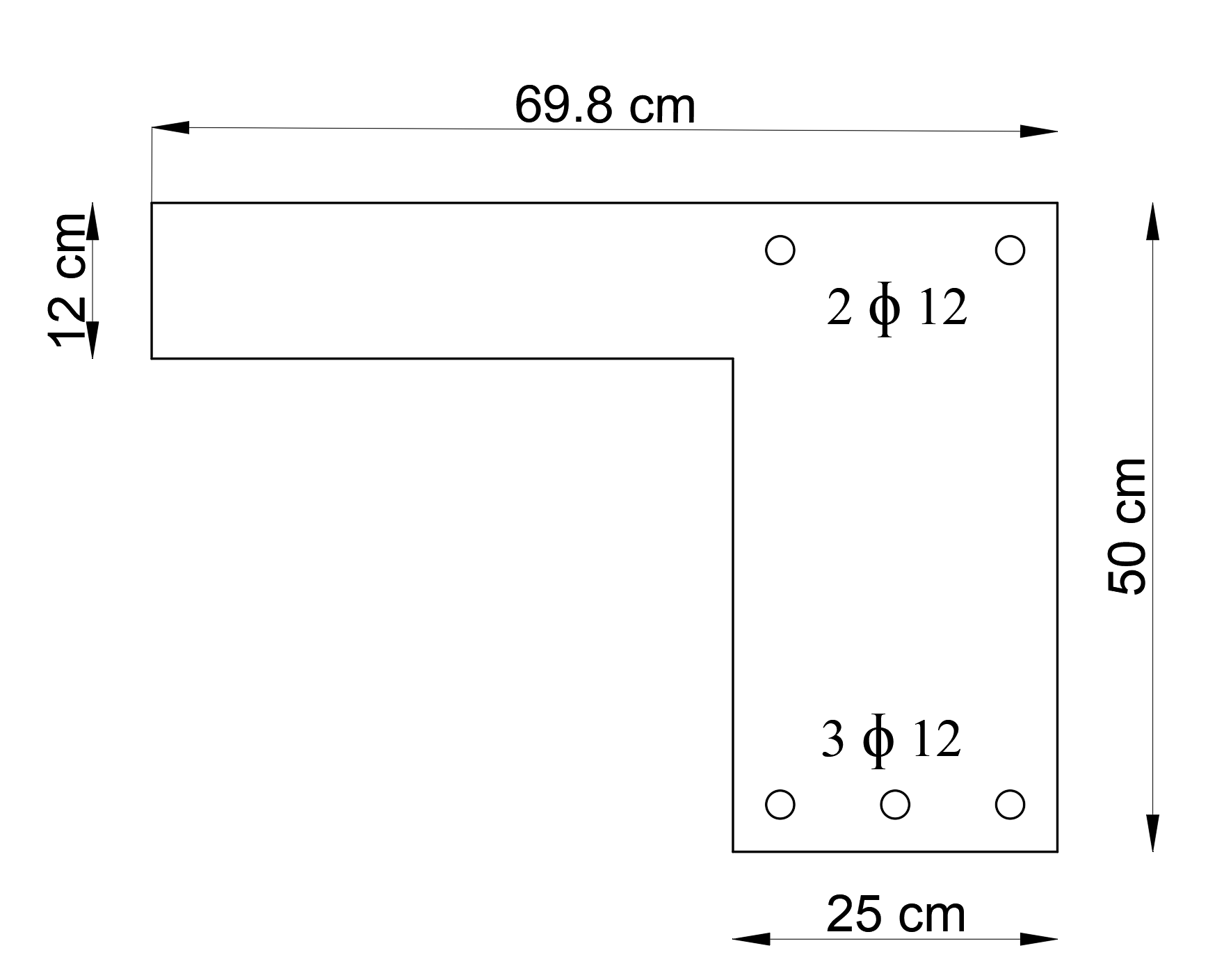
T-beam width 69.9 cm
-
Span length of beam ln = 5.60 m
Calculation of Section Center of Gravity and Gross Concrete Section Moment of Inertia
Moment of inertia of gross concrete section Ic, is calculated about controidal axis. Therefore, the axis of the center of gravity of the section, distance from centroidal axis of gross section, neglecting reinforcement, to top surface and distance from centroidal axis of gross section, neglecting reinforcement, to bottom surface of the section should be calculated.
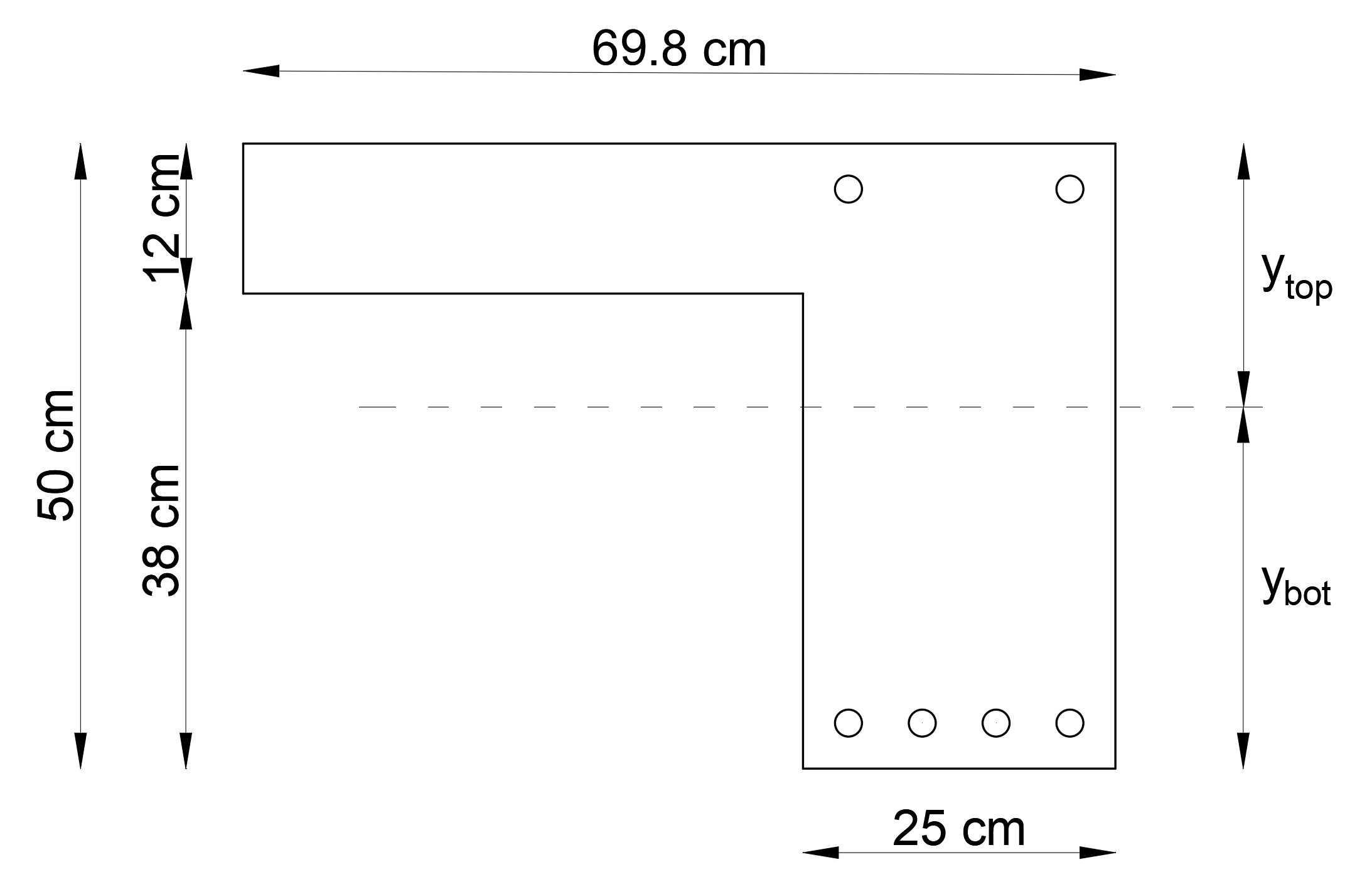
ytop : distance from centroidal axis of gross section, neglecting reinforcement, to top surface
ybot : distance from centroidal axis of gross section, neglecting reinforcement, to bottom surface
Moment of inertia of gross concrete section about controidal axis, Ic is calculated as follows
Section Cracking Control
The span, right and left moment values (Mmax) for the K06 beam are compared with the cracking moment Mcr of the member.
If Mmax ≤ Mcr moment of inertia of gross concrete section Ic is used for deflection.
If Mmax > Mcr Effective moment of inertia Ief is used for deflection.
Mcr is calculated in accordance with TS500 13.2. y is distance from centroidal axis of gross section, neglecting reinforcement, to tension surface. For this reason, Mcr values should be calculated separately both in the span and in the end regions.
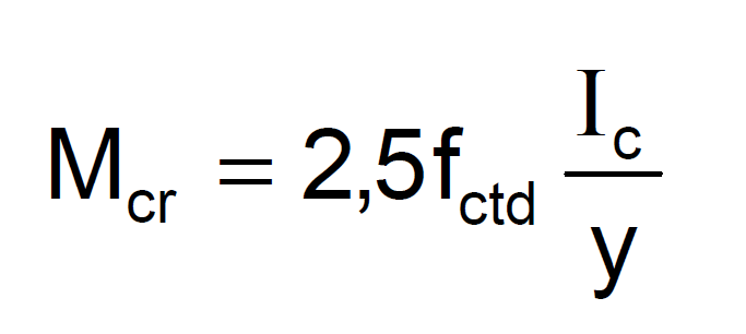
For the end region, the bending cracking moment Mcr is calculated as follows.
For the span region, the bending cracking moment M cr is calculated as follows.
Beam Cracking Control Under Constant Load (G) and Live Load (Q)
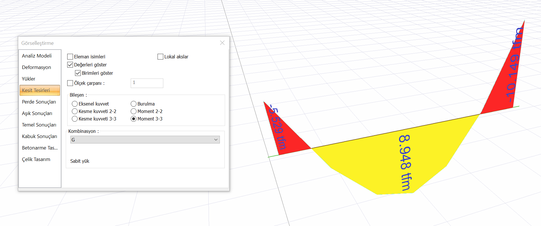
The moment diagram of the K06 beam for the G+Q loading combination is shown below.
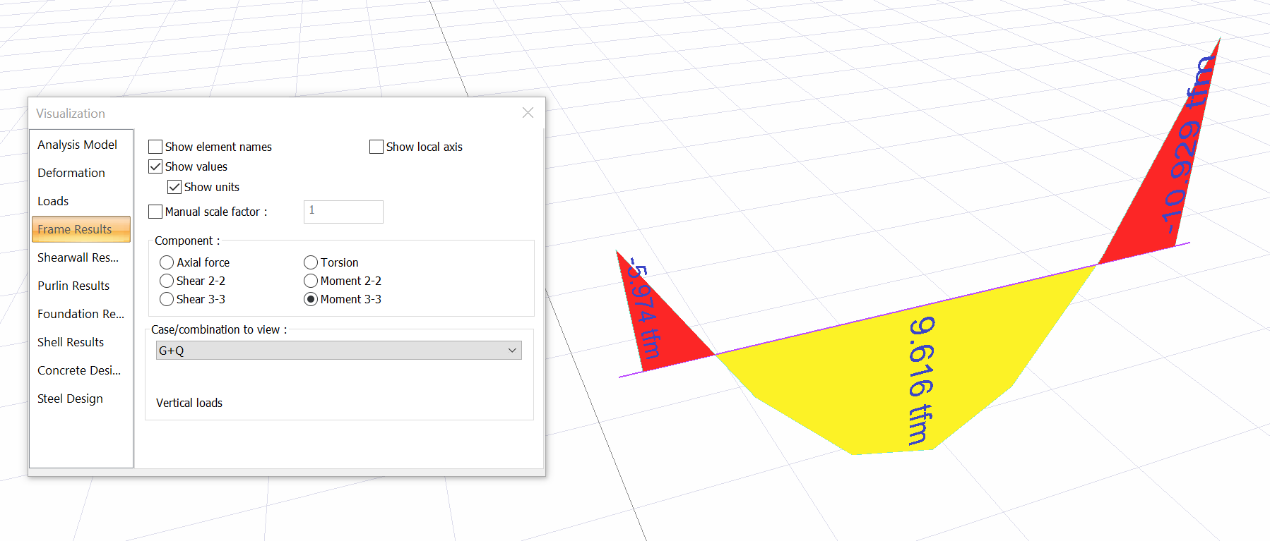
At the left end region, the bending cracking moment is calculated as Mcr = 6,208 tfm.
Since Mcr = 6.208 tfm > Mmax-left = 5.974 tfm, no cracking occurred at the left end region. For this reason, Moment of inertia of gross concrete section Ic value is used in the deflection calculation.
At the right end region, the bending cracking moment is calculated as Mcr = 6,208 tfm.
Since Mcr = 6.208 tfm ≤ Mmax-right = 10.929 tfm , cracking occurred at the right end region. For this reason, Effective moment of inertia Ieff value is used for calculation of deflection.
In the span region, the bending cracking moment is calculated as Mcr = 3.898 tfm.
Since Mcr = 6.208 tfm ≤ Mmax-span = 10.929 tfm , cracking occurred at the span. For this reason, Effective moment of inertia Ieff value is used for calculation of deflection.
|
Combination |
Left Moment (tfm) |
Span Moment (tfm) |
Right Moment (tfm) |
|---|---|---|---|
|
G+Q |
5.974 |
9.616 |
10.929 |
|
Çatlama Mometi |
< Mcr = 6.208 |
> Mcr = 3.898 |
> Mcr = 6.208 |
|
|
No cracking |
Cracked |
Cracked |
Moment of Inertia of Cracked Section Icr ve Effective Moment of Inertia Ieff Calculation for Span Region
In the calculation of the moment of inertia of the cracked section, the compression zone of the section and the reinforcement placement are taken into account. The figure below shows the span region for the opening region and the concrete compression region and reinforcement placement.
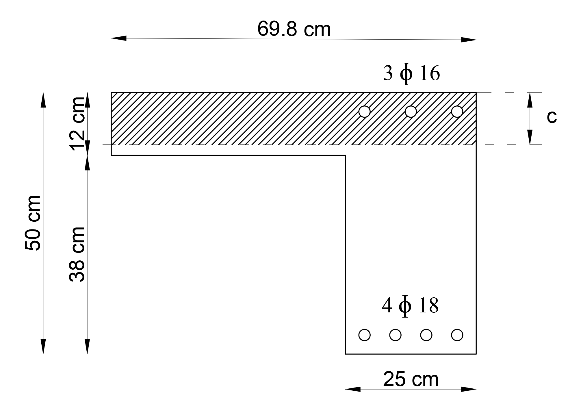
ρ is tension reinforcement ratio, ρ' is compression reinforcement ratio;, d is distance from extreme compression fiber to centroid of longitudinal tension reinforcement, and d' is concrete cover. olmak üzere, The location of the neutral axis kc and the height of the neutral axis c values incracked reinforced section are found as follows.
Moment of inertia of cracked section transformed to concrete Icr is calculated as follows for span region.
Effective moment of inertia Ieff is calculated as follows for span region.
Moment of Inertia of Cracked Section Icr ve Effective Moment of Inertia Ieff Calculation for Right End Region
In the calculation of the moment of inertia of the cracked section, the compression zone of the section and the reinforcement placement are taken into account. The figure below shows the right end region for the opening region and the concrete compression region and reinforcement placement.
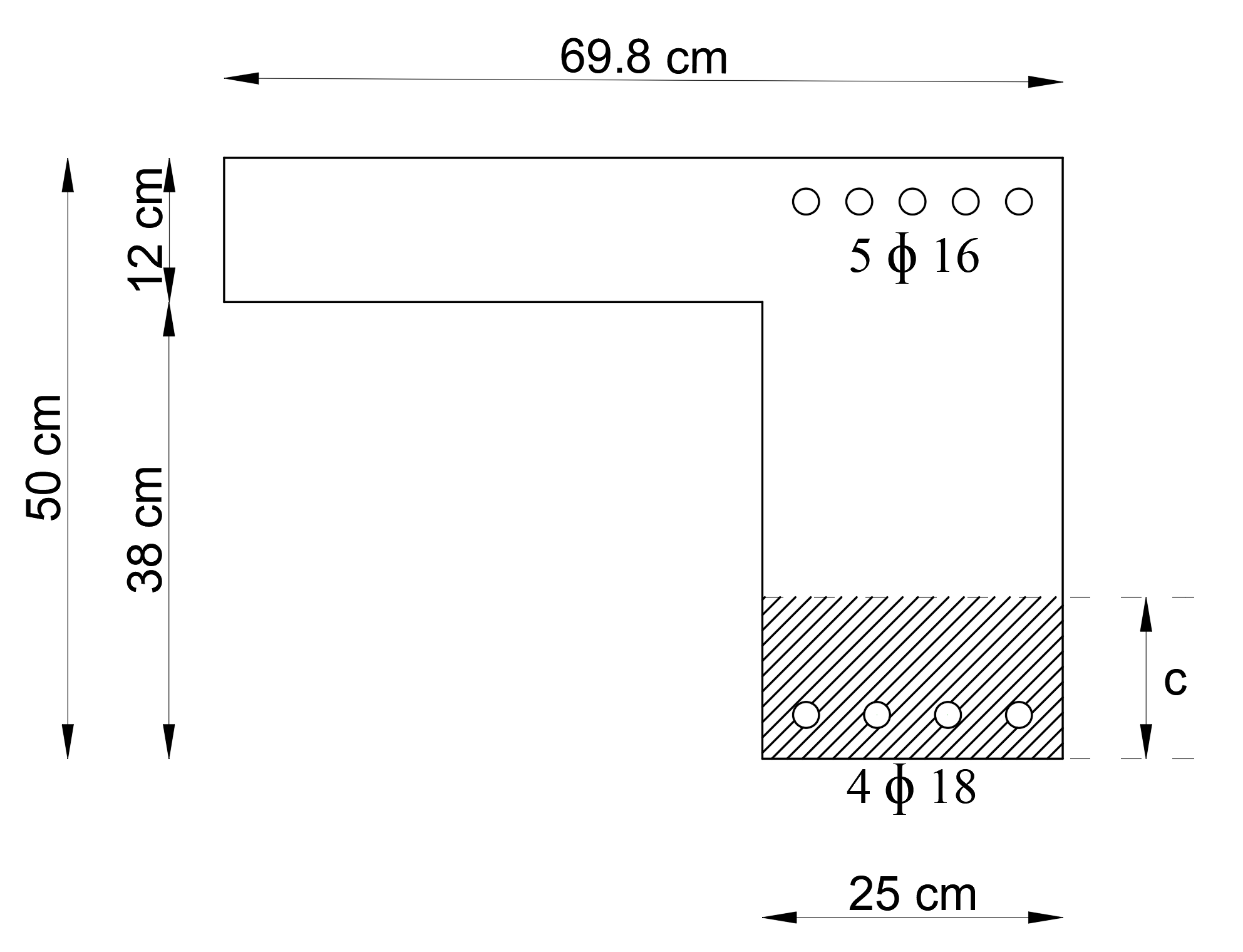
ρ is tension reinforcement ratio, ρ' is compression reinforcement ratio;, d is distance from extreme compression fiber to centroid of longitudinal tension reinforcement, and d' is concrete cover. olmak üzere, The location of the neutral axis kc and the height of the neutral axis c values incracked reinforced section are found as follows.
Moment of inertia of cracked section transformed to concrete Icr is calculated as follows for left end region.
Effective moment of inertia Ieff is calculated as follows for left end region.
Average Effective Moment of Inertia
The Average effective moment of inertia Ieff-ave of K06 beam is calculated by the effective moment of inertia Ieff values in left end, span and right end region. The deflection is calculated with Average Effective Moment of Inertia Ieff-ave value.
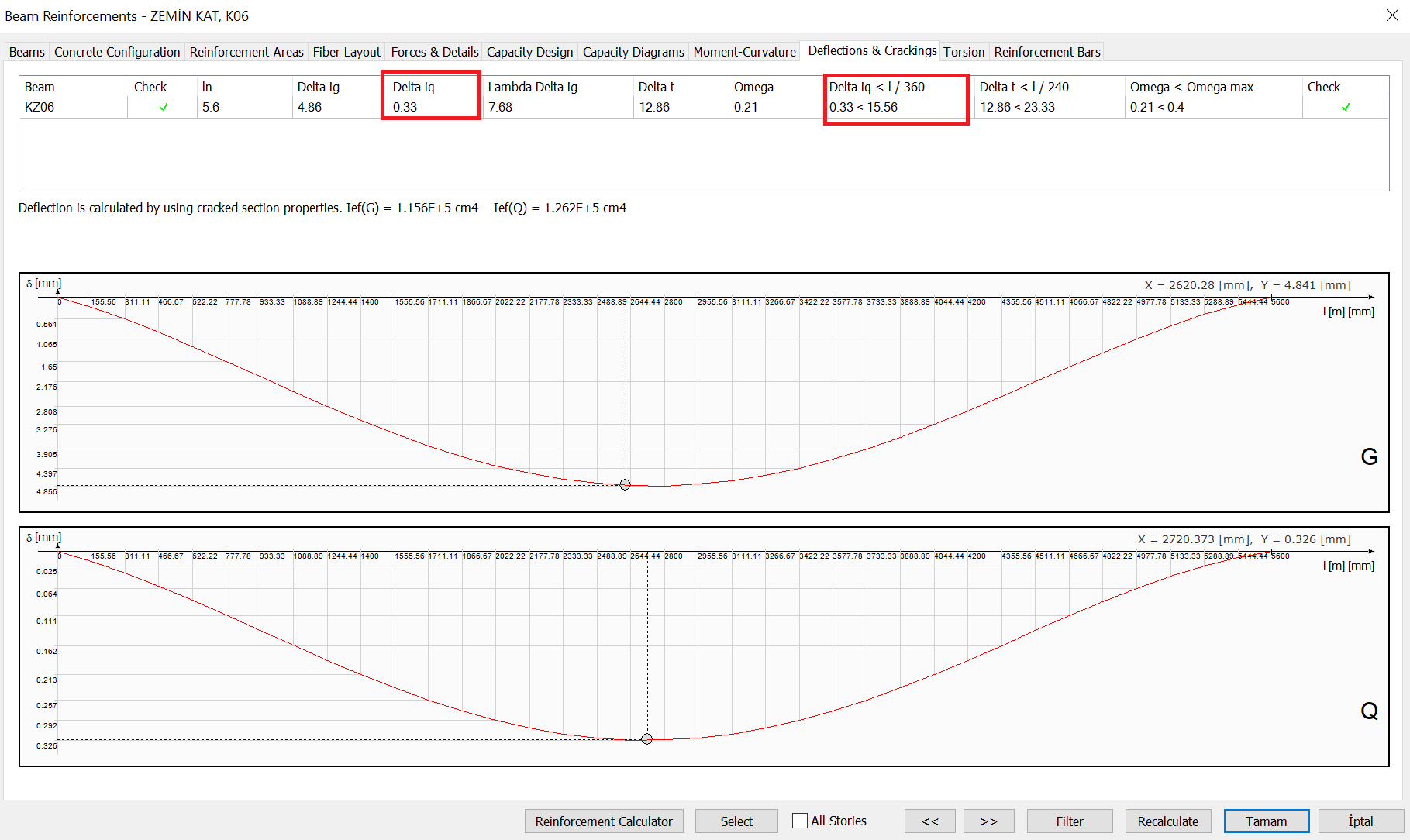
Instantaneous Deflection Under Live Load (Q) Effects
The moment diagram of the K06 beam for the Live Load (Q) effects is shown below.
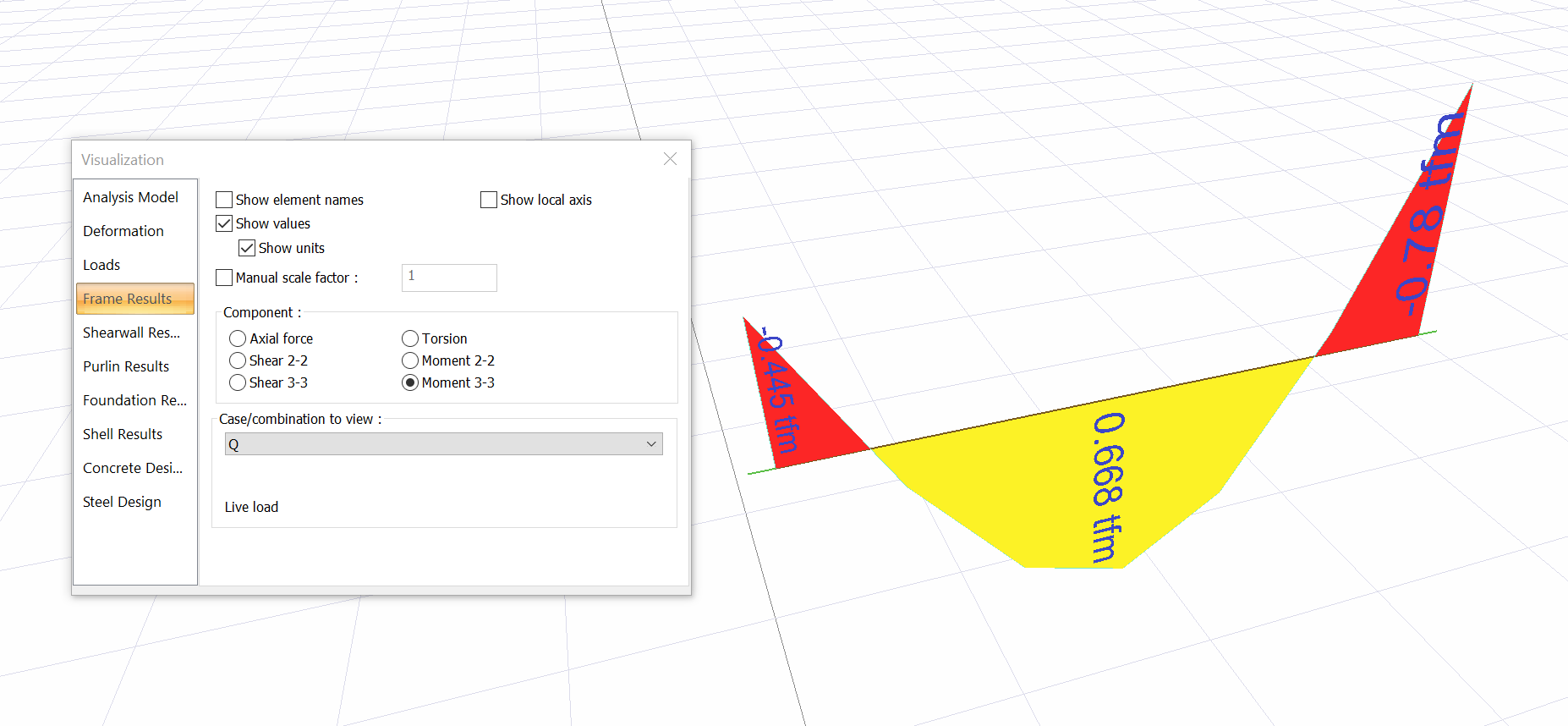
Instantaneous deflection due to live loads, δiQ
Deflection control;
δiQ = 0.30 mm < ln/360 =5600/360= 15.55 mm
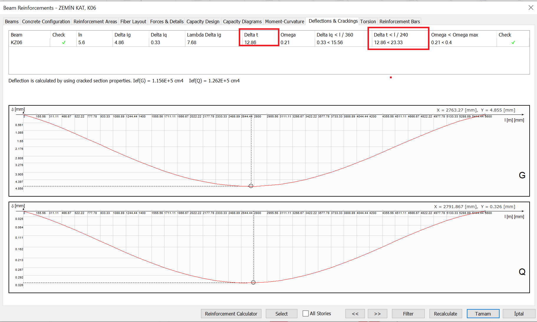
The deflection results of the K06 beam under the Live Load (Q) effect in the Beam Reinforcement window are shown below.
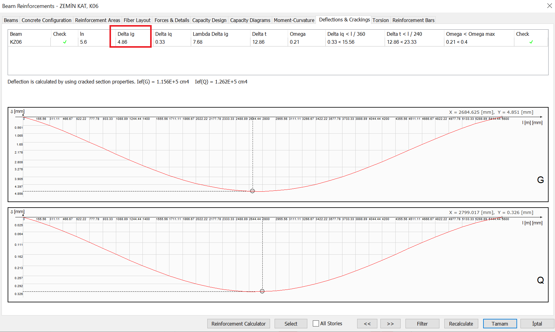
Instantaneous Deflection Under Dead Load (G) Effects
The moment diagram of the K06 beam for the DEad Load (G) effects is shown below.
Instantaneous deflection due to dead loads, δiG
The deflection results of the K06 beam under the Dead Load (G) effect in the Beam Reinforcement window are shown below.
Time Dependent Deflection
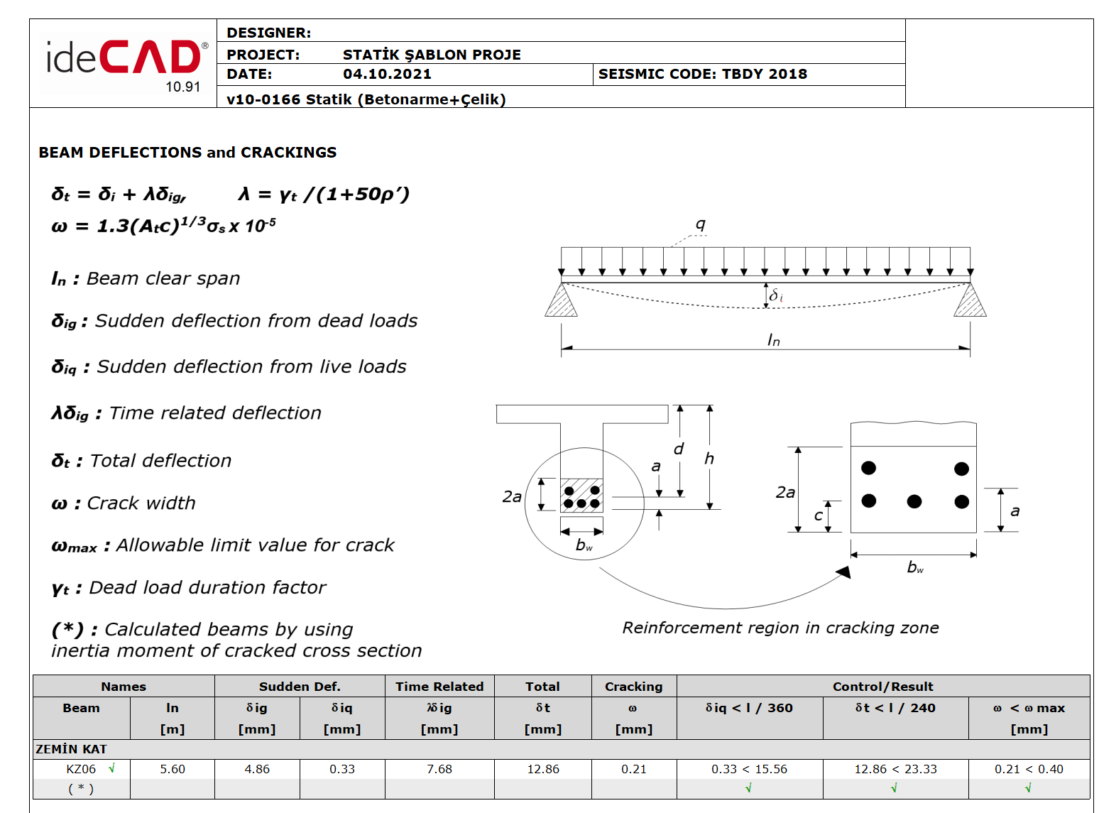
Total deflection calculation and permanent deflection coefficient formulas are shown below.
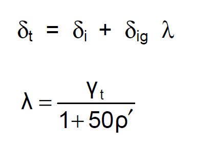
Permanent deflection multiplier γt is taken as 2.0 based on 5 years or more loading time in accordance with Table 13.2.
As' is area of the compression reinforcement and ρ' Compression reinforcement ratio;
When calculating the total deflection δt, the instantaneous deflection δiQ consisting of live loads, the instantaneous deflection δiG consisting of dead loads and the time-dependent deflection δiGλ are added. In this situation total deflection δt is calculated as follows.
Deflection control;
δt = 10.82 mm < ln/240 =5600/360= 23.33 mm
The total deflection results of the K06 beam in the Beam Reinforcement window under the effect of Dead and Live loads are shown below.
The results calculated above can also be checked in the Beam Deflections and Crackings Report .
Next Topic