
-
Cutting safety control of the columns is done automatically.
-
Shear force V e to be taken as basis for transverse reinforcement calculation in columns , Eq. It is calculated automatically with (7.5) .
-
For the calculation of M a and M u in Eq. (7.5) , 7.3.7.2 is applied automatically at the lower and / or upper ends of the column, if Equation (7.3) is fulfilled , and 7.3.7.3 is automatically applied if it is not .
-
The sum of the shear force calculated from the earthquake increased with D with the vertical loads , Eq. If V e calculated by (7.5) is smaller than V e , this shear force is used instead of V e condition is applied automatically.
-
Equation (7.6) is applied separately for both directions of the earthquake and the largest ∑ M p value obtained in each direction is taken as the basis in the distribution. Eq. (7.3) 's achieved even though the Eq. (7.5) ' one of M a or M ü 'are account 7.3.7.3 According done automatically.
-
In the calculation of M pa and M pü moments, N d axial forces which make these moments maximum in accordance with the direction of the earthquake are taken into consideration.
-
Moment M a at the lower end of columns connected to the foundation is automatically calculated as moment capacities according to 7.3.7.3 .
-
The shear force calculated by Equation (7.5) , V e , the shear force calculated under the combined effect of vertical loads and earthquake loads multiplied by the load coefficients, is not taken less than V d and it is also automatically checked whether it meets the conditions given in Eq. (7.7) .
-
In the calculation of the transverse reinforcement in the column confinement zones defined in 7.3.4.1 , if the shear force consisting only of seismic loads is greater than half of the total shear force in seismic condition and at the same time, the condition of N d ≤ 0.05 A c f ck is fulfilled, the contribution of the concrete to the shear strength V c = 0 is taken.
ICONS
A w = Effective body area of column cross-section
f ck = Characteristic cylinder compressive strength of concrete
f cd = Design compressive strength of concrete
f yd = Design yield strength of longitudinal reinforcement
L n = Free height of column between beams, free span of beam between column or curtain faces
M a = Moment at the lower end of the column's free height, based on the column shear calculation
M ü =At the upper end of the column's free height, the moment
M hü (i) = The moment at the upper end of the column is the moment at the work floor.
M ha (i) = It is the moment at the lower end of the column at the work floor.
M ha (i + 1) = It is the moment at the lower end of the column in the upper floor of the studied floor.
M hü (i-1) = It is the moment at the upper end of the column in the lower floor of the studied floor.
M ra = The moment of bearing strength calculated according to f cd and f yd at the lower end of the free height of the column or curtain
M rü =The moment of bearing strength calculated according to f cd and f yd at the upper end of the free height of the column or curtain
M ri = The moment of positive or negative bearing strength calculated according to f cd and f yd on the column or wall face at the left end i of the beam
M rj = Negative or positive moment of bearing strength calculated according to f cd and f yd on the column or wall face at the right end j of the beam
V c = Contribution of the concrete to the shear strength
V e = Shear force based on column transverse reinforcement calculation
Shear force to be based on transverse reinforcement calculation
7.3.7.1 - Shear force V e to be taken as basis for transverse reinforcement calculation in columns , Eq. It is calculated by (7.5) .
V e = ( M a + M ü ) / L n (7.5)
It is important for the calculation of M a and M ü whether the sum of the bearing strength moments of the columns at the node point is 20% more than the moments of the beams in both directions of the earthquake . For this reason, it is first checked whether the equation Equation (7.3) is fulfilled.
( M ra + M rü ) ≥ 1.2 ( M ri + M rj ) (7.3)
In case Eq. (7.3) is not provided:
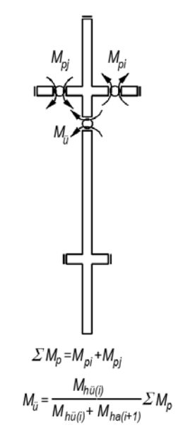
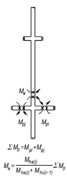
The sum of the torque capacity of the joint at the ends of beams Σ M p torque Eq. (7.6) is calculated by.
∑ M p = M pi + M pj (7.6)
M pa ≈1.4 M ra and M pi ≈1.4 M r can be taken. In the calculation of M pa and M pü moments, N d axial forces which make these moments maximum in accordance with the direction of the earthquake are taken into consideration.
M u 's account:
Calculation of M a :
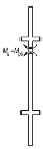
In case Equation (7.3) is met:
The moments calculated at the ends of the columns joining the node point are accepted as the moment capacities of the columns . (7.5) 't M a and / or M ü used instead.
M pa ≈1.4 M ra and M pi ≈1.4 M r can be taken.
M u 's account:
Calculation of M a :
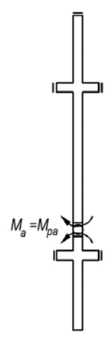
Moment M a at the lower end of columns connected to the foundation is also used as moment capacities.
V e 's account:
After determining M a and M u , Ln is calculated by considering column clear height.
V e = ( M a + M ü ) / l n (7.5)
The shear force calculated by Equation (7.5) , V e , the vertical loads multiplied by the load factors and the shear force calculated under the combined effect of earthquake loads shall not be taken less than V d .
And> = Vd.
And it must satisfy the conditions given by Equation (7.7) . If it cannot be achieved, the earthquake calculation should be repeated by increasing the column section dimensions as necessary.

Vr is the shear strength of the column section . It is calculated with the following steps according to TS500 .


As stated in TBDY 7.3.7.6 , in the calculation of transverse reinforcement in the column confinement zones, the contribution of concrete to the shear strength is V if the shear force consisting only of earthquake loads is greater than half of the total shear force in earthquake condition and at the same time the condition N d <0.05A c f ck is met. c = 0 is taken.
Next Topic