
With the Crane Settings command, settings such as beam and rail section selection, distance, drawing, wheel and bridge parameters are accessed.
Location of the Crane Settings Command
The Crane, which appears after the Crane command is run, is in the auxiliary toolbar.
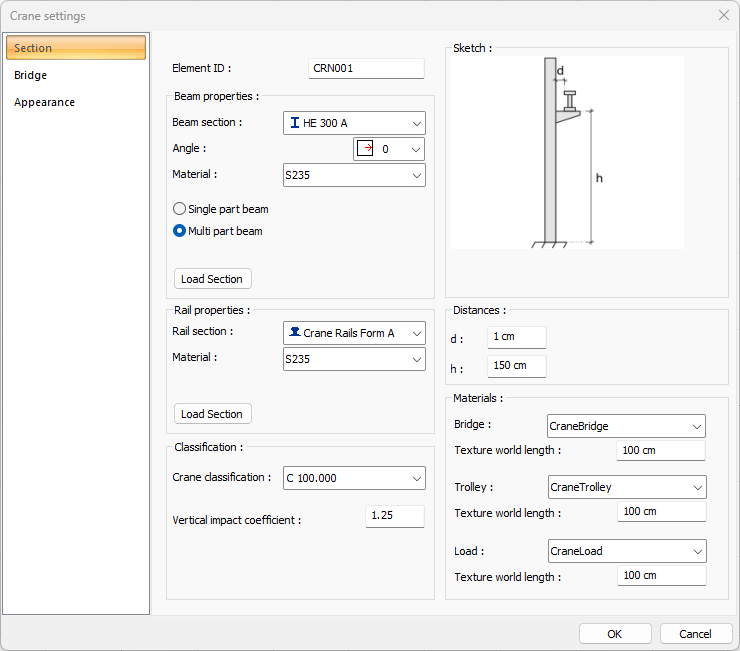
Section Tab
|
Specifications |
|---|
|
Element ID Name the crane. The program will automatically give a name. If wanted, the name of the crane can be changed on this line. |
|
Beam section The section of the beam on which crane sits is determined. The profiler used appears in the list. One of the previously defined profiles can be selected by clicking the list or a new profile can be selected from the dialog that opens when the Load Section button is clicked below. |
|
Angle It is the value that determines the angle of the profile with respect to the profile axis. According to the given angle value, the profile is drawn by rotating around its own axis. |
|
Material The material for the crane beam is selected. |
|
Single part beam/Multi part beam It determines whether the beam on which crane sits is divided at each column connection. If a single part beam is chosen, the crane beam is created in one piece, without splitting it across. |
|
Load section A list of available sections appears in the beam section list. The Load Section button is clicked to add a new section. After clicking the button, a new profile is selected from the drop-down list. |
|
Rail section The section of the rail on which the vehicle sits is determined. The profiles used appear in the list. One of the previously defined profiles can be selected by clicking the list or a new profile can be selected from the dialog that opens when the Load Section button is clicked below. |
|
Material The material for the crane rail is selected. |
|
Load section A list of available sections appears in the rail section list. The Load Section button is clicked to add a new section. After clicking the button, a new profile is selected from the drop-down list. |
|
Crane classification The crane classification is selected from the list. |
|
Vertical impact coefficient The vertical impact coefficient is entered. |
|
Sketch 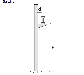
The distances are shown on the sketch. |
|
d The distance of the crane beam to the column is entered. |
|
h The height of the crane beam from the base is entered. |
|
Materials Bridge/Trolley/Load The material of the bridge, trolley and load to be covered in solid model is selected. It is coated with the selected material and displayed as such in the solid model. Click on the down arrow button with the left mouse button. The appropriate material is selected from the opened material list. |
|
Texture world length Texture length is entered. For example; If 1 meter is entered, the selected material texture is taken as 1 meter and covered on the selected object. If the texture is considered to be in the form of a square, the object surfaces are covered by lining up 1x1 textures side by side. |
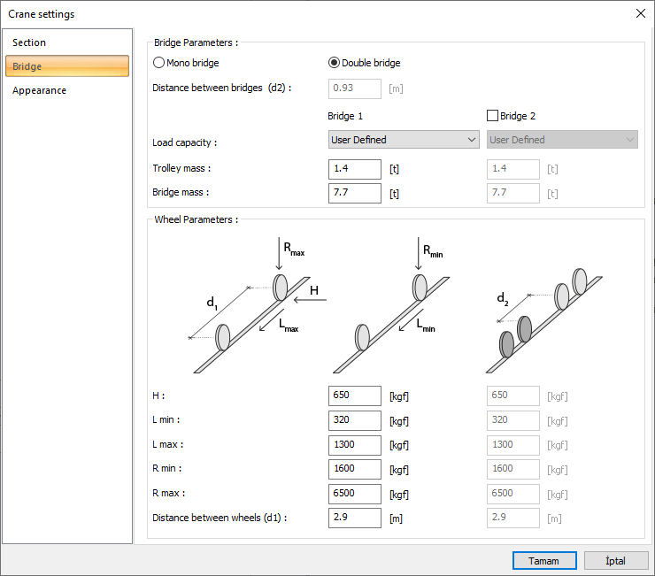
Bridge Tab
|
Specifications |
|---|
|
Bridge parameters 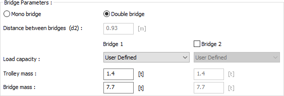
Determine whether the bridge wanted to project will be mono or double bridged. Arrange the loads and distances according to the figure given. |
|
Sketch 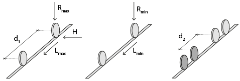
Singular parameters are shown on the figure. |
|
H Lateral force arising due to rail misalignment is entered. |
|
L min The minimum brake load created by the wheels is entered. |
|
L max The maximum brake load created by the wheels is entered. |
|
R min The minimum vertical load is entered. |
|
R max The maximum vertical load is entered. |
|
Distance between wheels (d1) The distance between the wheels is entered. |
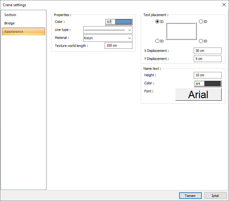
Appearance Tab
|
Specifications |
|---|
|
Color It is the color of the crane beam. The selection is made on the color palette that is opened by clicking with the left mouse button and holding the button down. |
|
Line type Line type of the line forming the crane is selected in the plan. Clicking the down arrow buttons to the right of the boxes opens the list of line types. From this list, the wanted line type is selected by clicking with the left mouse button. |
|
Material
The material to be covered is selected in the crane solid model. The crane is covered with the selected material and displayed as such in the solid model. Click on the down arrow button with the left mouse button. The appropriate material is selected from the opened material list. |
|
Texture world length Texture length is entered. For example; If 1 meter is entered, the selected material texture is taken as 1 meter and covered on the selected object. If the texture is thought to be in the form of a square, the object surfaces are covered with 1x1 textures arranged side by side. |
|
Text placement 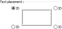
Determine the location where the name of the Crane will be written according to the figure in the dialog. |
|
X Displacement/Y Displacement X and Y coordinates of the crane dimension text are entered. If the dimension X value is positive, the dimension text shifts to the left, if it is negative, it shifts to the right. If the dimension Y value is positive, the dimension text will scroll up, and if it is negative, it will scroll down. |
|
Name text 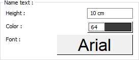
The height of the name of the crane is entered. The selection is made on the color palette that is opened by clicking with the left mouse button and holding the button down. The color box turns into the selected color. If the button below is clicked, the Font Settings dialog opens. Column Name Text, font type is set from this dialog. |
Next Topic
Related Topics