
-
The selection and definition of the earthquake acceleration records for the mode summation method in the time history is under user control.
-
The scaling of the selected earthquake acceleration records is done automatically.
-
After the acceleration records are defined, the earthquake calculation is made automatically with the modal summation method in the Time domain.
Symbols
a nR (X, Y) ( t ) = Time-dependent linear modal pseudo-acceleration of the nth vibration mode under the joint action of (X) and (Y) earthquake ground motion components simultaneously[m / s 2 ]
d n ( X, Y) ( t ) = Time-dependent linear modal displacement of the nth vibration mode under the joint action of the earthquake ground motion components (X) and (Y) simultaneously[m]
d ' n (X, Y) ( t ) = Time dependent linear linearity of the nth vibration mode under the joint effect of (X) and (Y) earthquake ground motion components at the same time.modal velocity [m / s]
d '' n (X, Y) ( t ) = Time-dependent linear modal acceleration of the nth vibration mode under the joint action of (X) and (Y) earthquake ground motion components simultaneously [m / s 2 ]
f ixn (X, Y) = The variation of the modal earthquake load acting on the i'th floor in the x direction in the nth vibration mode under the joint effect of (X) and (Y) earthquake ground motion components at the same time [kN]
H i = The height [m] of the i'th floor measured from the base of the upper section in the upper section above the basement floors of the building .base shear modal effective mass [t]
r max (X) = (X) combined typical largest modal response magnitude corresponding to any response magnitude (displacement, relative story displacement, internal force component) for the earthquake direction
r n (X) = Typical unit modal behavior magnitude
r (X, Y) ( t ) corresponding to any action magnitude (displacement, relative floor displacement, internal force component) for the earthquake direction in the nth natural vibration mode (X ) = Typical response magnitude corresponding to any action magnitude (displacement, relative floor displacement, internal force component) under the joint effect of (X) and (Y) earthquake ground motion components simultaneously with respect to time
r n (X, Y) ( t ) = Typical modal response magnitude corresponding to any action magnitude (displacement, relative storey displacement, internal force component) in the nth vibration mode under the joint action of the (X) and (Y) earthquake ground motion components at the same time.
T n = natural vibration period of the nth mode [s]
u g (X) ( t) = (X) the variation of the ground acceleration component defined in the direction of the earthquake with time [m / s 2 ]
ü g (Y) ( t ) = (Y) the change of the ground acceleration component defined in the direction of the earthquake with time [m / s 2 ]
V txn ( X, Y) ( t ) = Simultaneously under the joint effect of (X) and (Y) earthquake ground motion components in the nth vibration mode, the variation of the modal base shear force with respect to time
Γ n (X) = (X) for the earthquake direction The modal contribution factor ξ n for the nth vibration mode
= modal damping ratio of the nth vibration mode
ω n = natural vibration angular frequency of the nth vibration mode [rad / s]
If the Mode Addition Method is applied in the time history , at least 11 earthquake ground motion sets must be used. According to the method, the acceleration records in two horizontal directions perpendicular to each other are automatically activated together at the same time in the direction of the main axes (X) and (Y) of the carrier system . Then, the axes of the acceleration records are rotated 90 o and the calculation is repeated automatically . Selection and scaling of earthquake records to be used in calculations should be made according to TBDY 2018 2.5 . See Earthquake Ground Motion Records in Time History for detailed information .
The behavior sizes will be found as the average of the largest absolute values of the results to be obtained from each of at least 2 × 11 = 22 calculations made according to the following equation.
-
The motion equations detailed below are automatically solved by Newmark method .
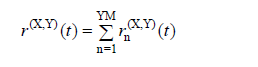
In a typical nth vibration mode for an earthquake acting simultaneously in two horizontal earthquakes directions, the typical modal behavior magnitude corresponding to the action magnitudes (displacement, relative storey displacement, internal force components) is Calculation of Combined Response Parameters and Scaling Design Values of Combined Response (4.8.2.1) , change over time r n (X, Y) ( t ) , the following equation is calculated by:
Here r n (X) is the typical unit modal behavior magnitude for the earthquake direction (X) selected as the calculation reference direction , and a nR (X, Y) ( t ) is defined in terms of time with the following equation for the nth vibration mode. corresponds to reduced modal pseudo-acceleration .
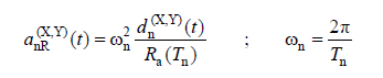
ω n denotes the natural angular frequency of the typical nth vibration mode, d n (X, Y) ( t ) is the modal displacement calculated by the above equation .
Linear modal displacement , d n (X, Y) ( t ) , under the combined effect of earthquake ground motion components (X) and (Y) simultaneously, the modal single degree of freedom system belonging to the nth mode in the time domain of the equation of motion given below It is obtained from the linear solution:
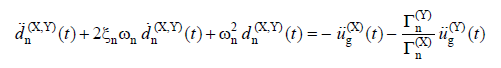
Here, ü g (X) (t) and ü g (Y) (t) perpendicular to each other (X) and (Y) ground accelerations in earthquake directions and d n (X, Y) (t) is the time of the nth vibration mode. shows the connected linear modal velocity and acceleration . The time increment to be taken as basis in the calculation is not greater than T n / 10.
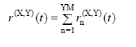
Under the influence of the earthquake defined in (X) and (Y) directions, the variations of the behavior magnitudes such as internal force components, displacement and relative floor displacement with time, r (X, Y) ( t ) , simultaneous modal contributions calculated for each vibration mode, r n (X, Y) ( t ) is obtained by direct addition.
In a typical nth vibration mode under the influence of an earthquake defined in (X) and (Y) directions, the modal base shear force of the carrier system in the x-axis direction and the corresponding base overturning moment varies with time V txn (X, Y) ( t ) and M oxn (X, Y) ( t ) are calculated by the following equations:
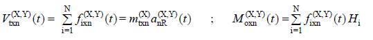
The modal contributions of these quantities are collected in the time domain.
Next Topic