-
The calculated overturning moments are performed automatically as specified in Example BA-2 in the TBDY 2018 Training Application Examples book.
Symbols
BYS = Building Height Class
c = Distance between the cross-section gravity centers of the shear walls with tie beams (with gaps)
DTS = Earthquake Design Class
D = Strength Reduction Coefficient
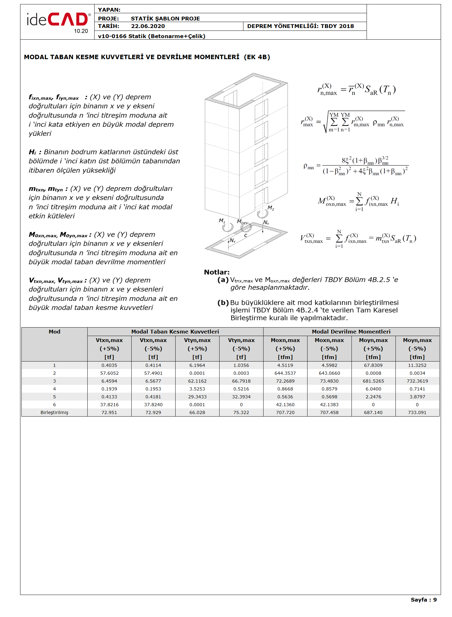
f (X) ixn, max = (X) nth direction of the building's x axis for earthquake direction The largest modal earthquake load acting on the i'th floor in natural vibration mode
H i = The height of the i'th floor measured from the base of the upper section in the upper section above the basement floors of the building
M DEV =Overturning moment caused by earthquake loads at the base of the reinforced concrete shearwalls or braced frame
M 1, M 2 = Bending moments at the base obtained from the earthquake effect in the shearwall parts forming the tie-beam shearwall
M o = The total tipping moment at the base due to earthquake loads for the whole building
M (X) oxn For the earthquake direction max = (X), the maximum modal base overturning moment of the nth vibration mode of the building in the x axis direction
m (X) txn =(X) for the earthquake direction, the base shear force modal effective mass of the nth vibration mode of the building in the x-axis direction
N v = Equal tensile and pressure at the base of the curtain parts as the sum of the shear forces generated in the tie beams of the tie beam curtain under the earthquake effect over the entire height of the curtain. axial forces
R = Carrier System Behavior Coefficient
S aR (T n ) = reduced design spectral acceleration of the nth vibration mode
V (X) txn, max =(X) largest modal base shear force of the building's nth vibration mode in the x-axis direction for the earthquake direction
The sum of the overturning moments resulting from seismic loads at the bottom of the walls used in TBDY Articles 4.3.2.3 , 4.3.4.5 and 4.3.4.6 , M DEV , values according to 4.5.3.7 (d) or 4.5.3.8 (c) for non- gap walls , It is calculated according to 4.5.4.3 for curtains with gaps . The M o value of the total overturning moment occurring at the base from earthquake loads for the whole building is calculated using the 4.8.2 mode combination method described in Annex 4B.2.5 .
The base tipping moment of the bond beam (hollow) wall is calculated by the following equation:

Here, as the total tipping moment at the base of the wall with M DEV bond beam (hollow), the bending moments obtained at the base due to the earthquake effect in the curtain parts forming the wall with M 1 and M 2 bond beams, and N V as the sum of the shear forces formed in the bond beams under the earthquake effect over the whole wall height, It corresponds to equal tensile and pressure axial forces formed at the base of the curtain parts. c shows the distance between the cross-section gravity centers of the curtain parts.
To use in the above equation , the p arameters M 1 , M 2 , N V and M DEV are calculated as follows:
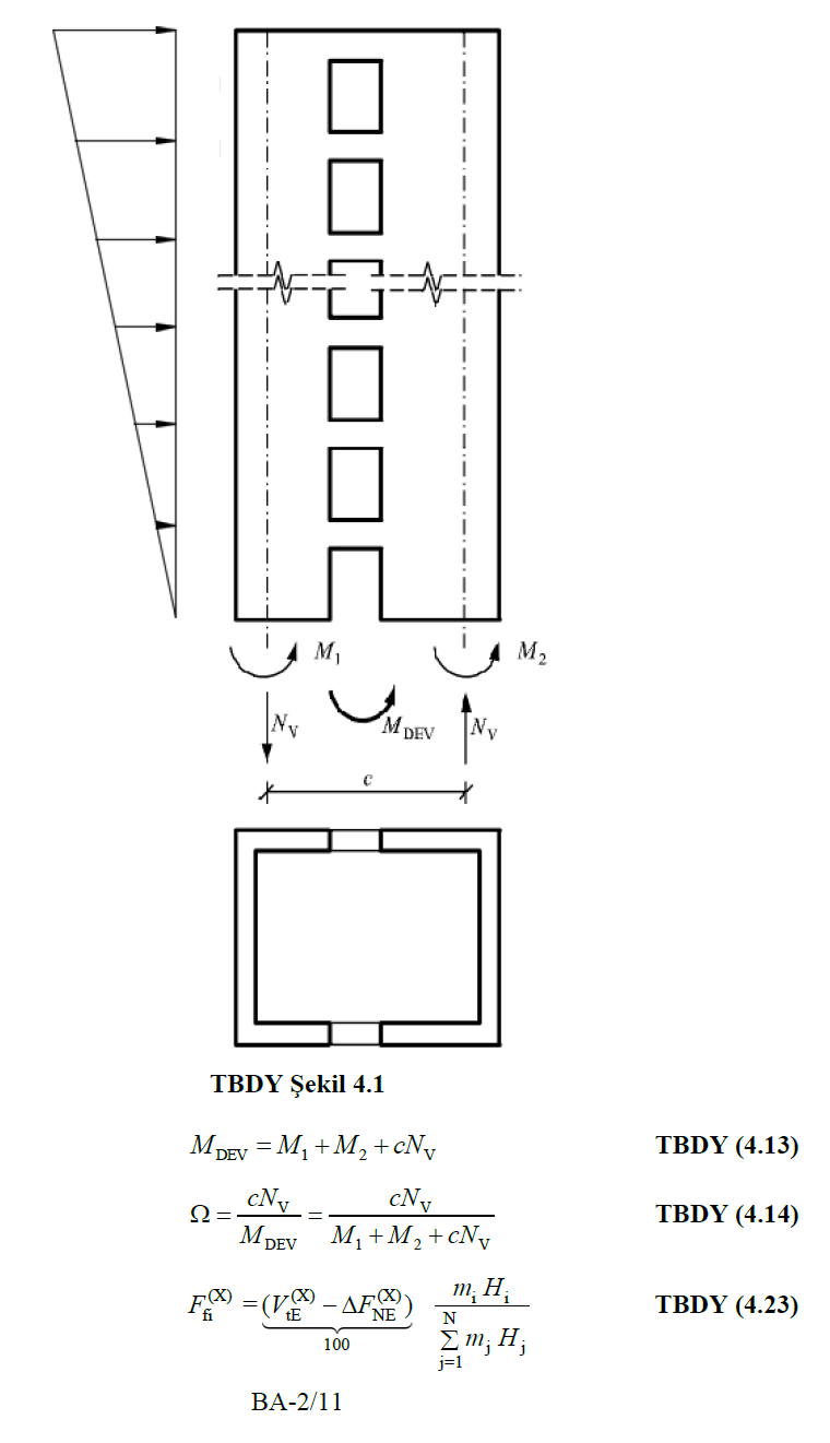
The element group to be controlled with gaps is separated from the system, the inverted triangle unit is automatically loaded according to the weight of the floors . In this calculation, the value of unit loading is not important, the curtain group and tie beams separated from the system take loads in proportion to their own rigidity. In the automatic calculation, the force to be applied to the curtain group is determined. Then this force is distributed to each floor depending on its own weight using the following equations. The distributed force is applied to the center of the wall group and the parameters M 1 , M 2 , N V obtained as a result of this effect are replaced in the above equation.
The M o value of the total overturning moment occurring at the base from earthquake loads for the whole building is calculated using the 4.8.2 mode combination method described in Annex 4B.2.5 . In a typical nth vibration mode for the (X) earthquake direction (X) given in accordance with Annex 4B.2.5 , the largest modal base shear force V (X) txn, max and corresponding maximum base overturning moment M ( X) oxn, max Equation (4B.7) is calculated by:

Below is a sample report where the modal base shear forces and the corresponding base overturning moment are calculated according to TBDY Annex 4B.2.5.