
With the planar texture mapper command, the continuity of the material assigned to the surfaces of different objects such as walls, columns, beams on the same facade can be achieved.
Location of the Planar Texture Mapper Command
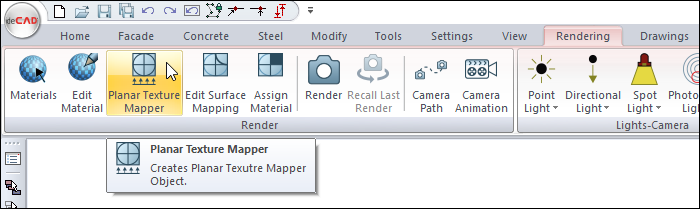
You can access it under the ribbon menu Rendering tab, Render title in the architectural program.
Usage Steps
-
Click the Planar Texture Mapper icon.
-
The surfaces whose material is wanted to be edited are selected.
-
Click the right mouse button and click the Finish Selection line.
-
Determine the starting point of the texture mapper. Your material will be defined to objects based on that point.
-
View point is determined by clicking the left mouse button on the plan screen.
-
The preview of arrows showing the direction of view will occur and rotate based on mouse movement.
-
By clicking the left mouse button, the arrows showing the viewing direction are fixed.
-
The Projection Parameters dialog opens automatically.
-
After making the necessary settings, the texture editing process on the selected surfaces is completed by pressing the OK button.
|
Usage step |
|---|
|
Before planar texture mapper 
|
|
Selecting the surfaces whose material is desired to be edited 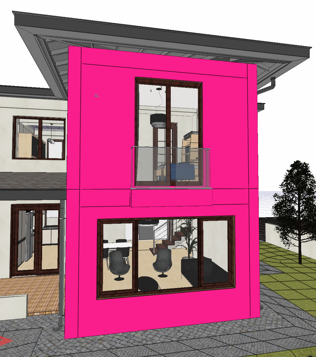
|
|
Determining the starting point 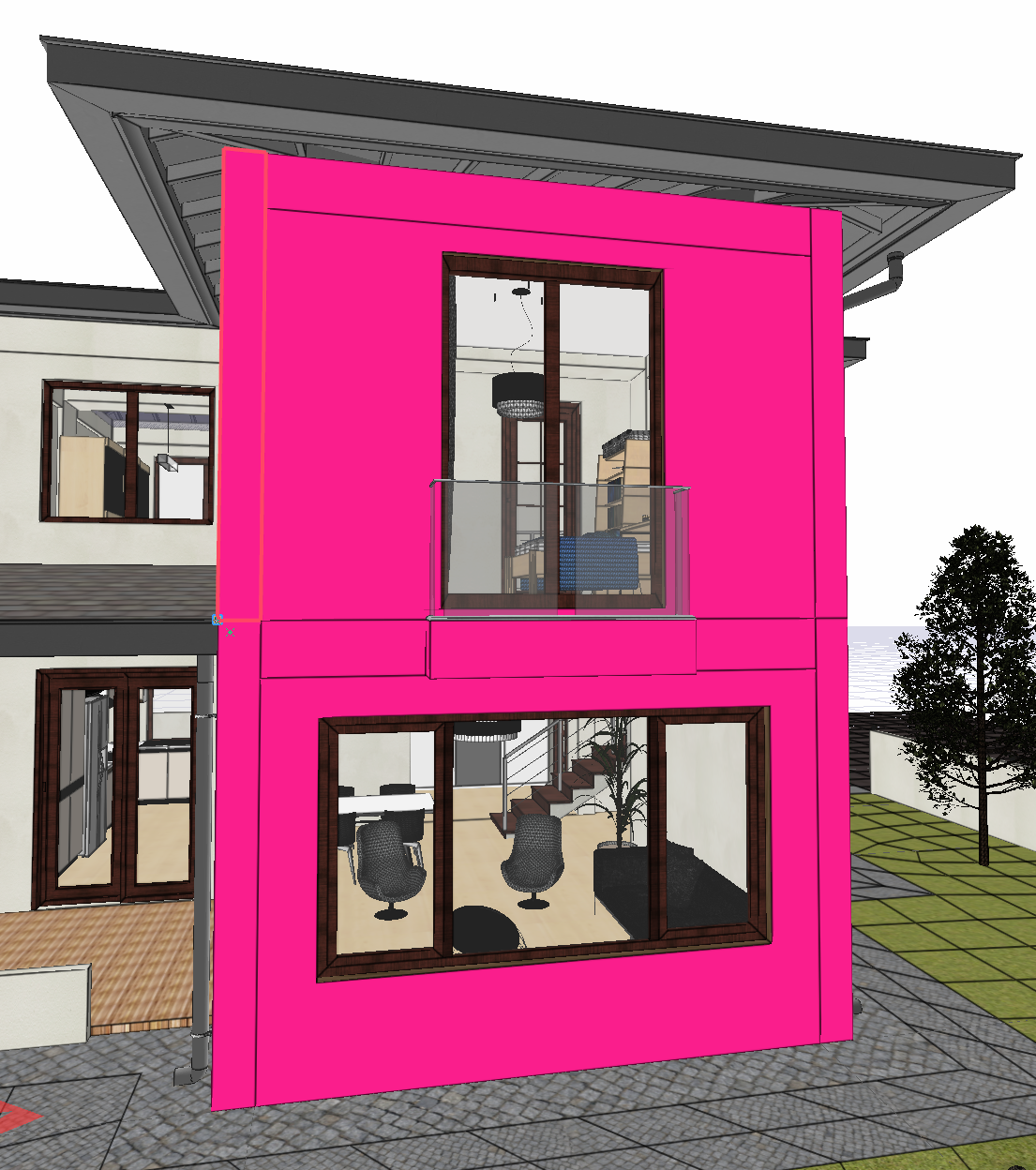
|
|
Determining the viewing direction 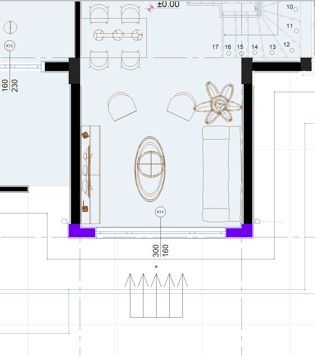
|
|
Making the settings 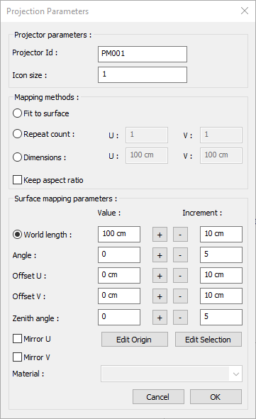
|
|
After planar texture mapper 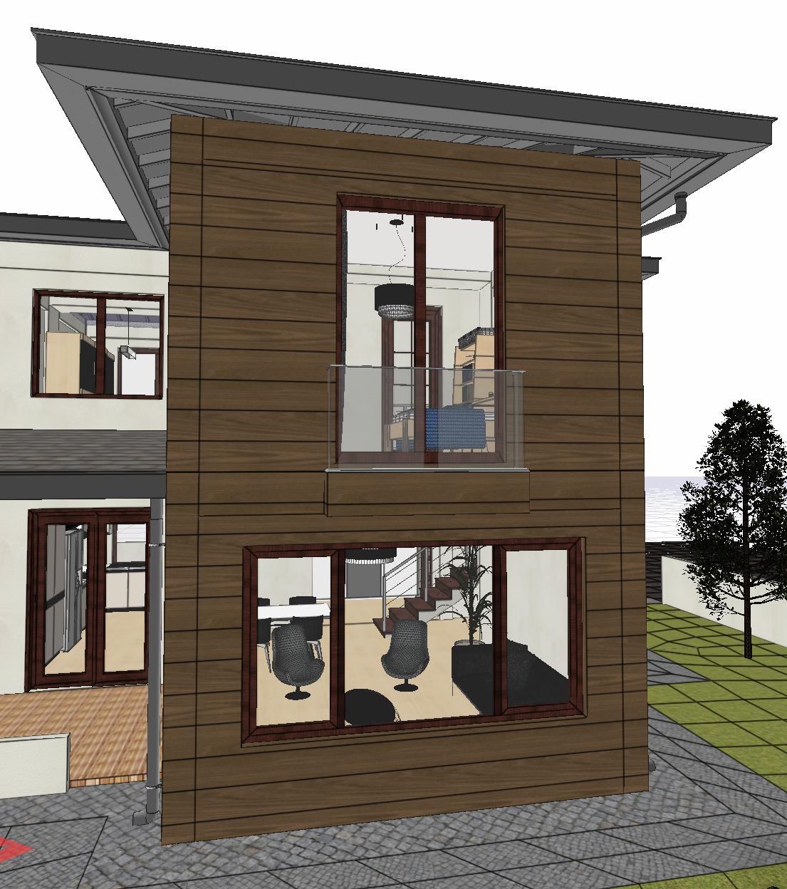
|
Projection Parameters

|
Specifications |
|---|
|
Projector Id The name of the projector that will appear in the plan. |
|
Icon size The size of the icon indicating the arrangement is determined. |
|
Fit to surface Places the texture to cover the selected surfaces. |
|
Repeat count Repeats the texture for the values entered on the selected surfaces. |
|
Dimensions Texture length is determined by entering values in two directions. |
|
Keep aspect ratio If checked, the texture is edited by entering a value in the U box from the number of repetitions and dimensions lines. |
|
Worl length Texture length is entered. |
|
Angle 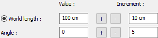
Texture angle is entered. |
|
Offset U 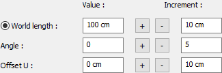
The motion value of the texture in the x-plane is entered. |
|
Offset V 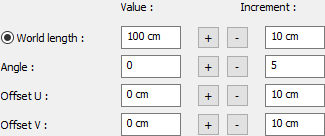
The motion value in the y-plane of the texture is entered |
|
Zenith angle 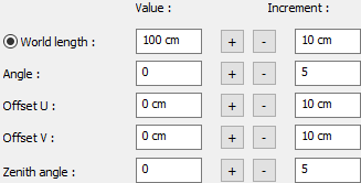
The angle value in the z plane of the texture is entered. |
|
Mirror U Symmetries the texture with respect to the y plane. |
|
Mirror V Symmetries the texture with respect to the x-plane. |
|
Edit origin The starting point is determined again. |
|
Edit selection Add/remove selected surfaces. |