
-
Three-dimensional interaction failure surface of a column is calculated automatically
İnternational Design Codes
ACI 318-19 : Column Combined Flexural and Axial Design
TSC 2018 : Axial Force and Biaxial Moment Interaction for Columns
Notation in ACI 318-19
Ag = gross area of concrete section, in2
As = area of nonprestressed longitudinal tension reinforcement, in2
Ast = total area of nonprestressed longitudinal reinforcement, in2
α = depth of equivalent rectangular stress block, in.
bw = width of compression face of member, in.
c = distance from extreme compression fiber to neutral axis, in.
Cc = concrete compressive force, lb
Cs = reinforcement tension force, lb
d = distance from extreme compression fiber to centroid of longitudinal tension reinforcement, in.
D = dead load
E = earthquake load
fc' = specified compressive strength of concrete, psi
fy = specified yield strength for nonprestressed reinforcement, psi
L = live load
Lr = roof live load
Mn = nominal flexural strength at section, in.-lb
Mu = factored moment at section, in.-lb
Pn = nominal axial compressive strength of member, lb
Pn,max = maximum nominal axial compressive strength of a member, lb
Pnt = nominal axial tensile strength of member, lb
Pnt,max = maximum nominal axial tensile strength of member, lb
Po = nominal axial strength at zero eccentricity, lb
Pu = factored axial force; to be taken as positive for compression and negative for tension, lb
R = rain load
S = snow load
Tn = nominal torsional moment strength, in.-lb
Tu = factored torsional moment at section, in.-lb
Vn = nominal shear strength, lb
Vu = factored shear force at section, lb
W = wind load
ϕ = strength reduction factor
εt = net tensile strain in extreme layer of longitudinal tension reinforcement at nominal strength, excluding strains due to effective prestress, creep, shrinkage, and temperature
β1 = factor relating depth of equivalent rectangular compressive stress block to depth of neutral axis
Required strength
Required strength is calculated in accordance with the factored load combinations. Combined Axial and Flexural Required strengths of a column occur simultaneously for a column. Therefore, for each applicable factor load combination specified in Codes.
Design strength
Combined nominal flexural and axial strength are calculated as shown below.
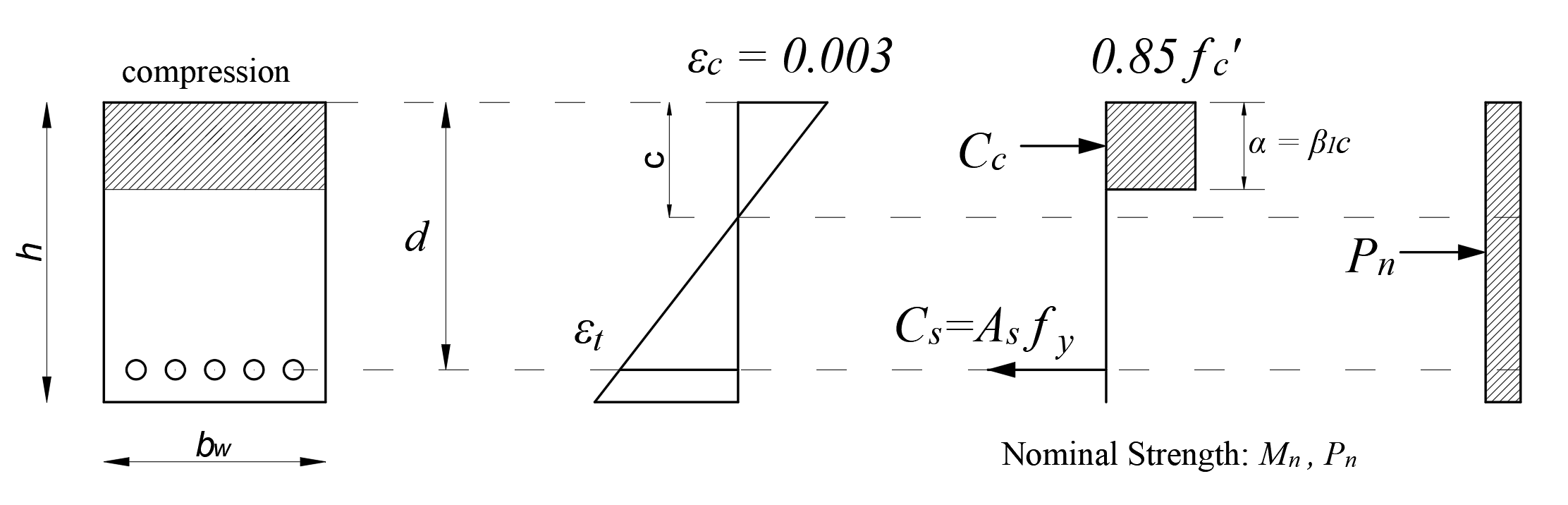
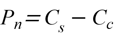
From the equation of equilibrium:
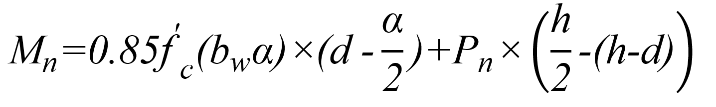
Nominal flexural strength:
Next Topic