-
At the joints of columns and beams, all six degrees of freedom are automatically taken into account.
ICONS
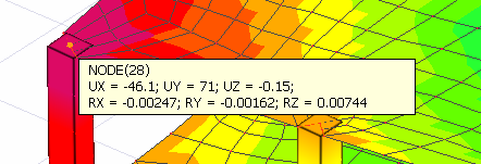
UX = The displacement of the joint point in the (X) direction in thethree-dimensional analysis model
UY = The translation of the joint point in the (Y) direction in thethree-dimensional analysis model
UZ = The translation of the joint point in the (Z) direction in thethree-dimensional analysis model
RX = Rotation of the joint point around the (X) axis in the three dimensional analysis model
RY = Rotation of the joint point around the (Y) axis in the three dimensional analysis model
RZ = The rotation of the joint point around the (Z) axis in the three dimensional analysis model
Beams and columns are modeled with rod finite elements containing all six degrees of freedom, three translational and three rotational freedoms. In this case, the displacements at the nodal points as a result of the three-dimensional analysis have six values, three translations and three rotations. The values shown by UX, UY and UZ in the picture below are the shifts occurring in the (X), (Y) and (Z) directions, respectively. The values represented by RX, RY and RZ are the rotations that occur around the (X), (Y) and (Z) axis respectively.
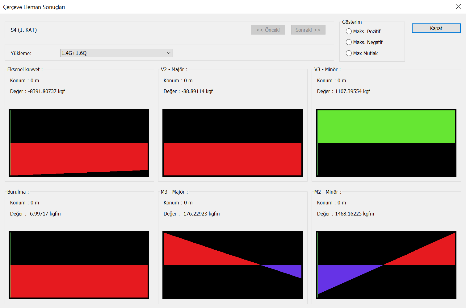
Similarly, in rod finite elements, there are six internal forces corresponding to all six degrees of freedom. These internal forces are the axial force defined according to the local axis of the bar, and the shear forces V2, V3 and the torsion moment and the bending moments M2, M3. Element Local Axes detailed explanation has been made on this subject under the heading Element Local Axes .