
-
Shear force, V e , which will be taken as basis for the transverse reinforcement calculation in beams , is calculated automatically with Equation (7.9) in a way to give unfavorable results separately for earthquakes from left to right or from right to left .
-
If the sum of D and increased shear force calculated from the earthquake together with the vertical loads is less than V e calculated by Equation (7.9) , the condition of using this shear force instead of V e is automatically applied.
-
It is automatically checked whether the calculated design shear force, V e , meets the conditions given in Equation (7.10) .
-
In the calculation of beam transverse reinforcement, the contribution of concrete to shear strength, V c , is determined automatically according to TS500 .
-
In the calculation of the transverse reinforcement in the beam confinement regions, if the shear force consisting of only seismic loads is greater than half of the total shear force in earthquake condition, the condition that the contribution of the concrete to the shear strength is taken as V c = 0 .
ICONS
A c = Element full cross-section concrete area
A sw = Shear reinforcement total cross-sectional area
b w = Body width of beam
D = Extra Strength Coefficient
d = Useful height of beam
f ck = Characteristic cylinder compressive strength of concrete
f cd = Design compressive strength of concrete
f yk = Characteristic yield strength of longitudinal reinforcement
f yd = Design yield strength of longitudinal reinforcement
f ywd = Transverse reinforcement design yield strength
l n = free height between the columns of beams, the free span between the beam column or wall faces
M pi = beam left end i wherein the column face f ck f yk and calculated taking into account the increase in strength of steel positive or negative moment capacity
M pj = positive or negative moment capacity calculated by taking into account f ck , f yk and the strength increase of the steel on the column face at the right end j of the beam
M ri =The moment of positive or negative bearing capacity calculated according to f cd and f yd on the column or wall face at the left end of the beam
M rj = The right end of the beam is negative or positive calculated according to f cd and f yd on the column or wall face at j. bearing strength moment
N d = Axial force calculated under the combined effect of vertical loads and earthquake loads multiplied by the load factors
V c = Contribution of concrete to shear strength
V cr = Shear strength of the section
V d = Shear force calculated under the combined effect of vertical loads and earthquake loads multiplied by the load coefficients
V dy = Simple beam shear force resulting from vertical loads not multiplied by the load coefficients in any section of the beam
V e = Shear force taken as basis in the beam transverse reinforcement calculation
V r = Beam shear strength of cross section
V w = shear reinforcement contribution to shear strength
Shear Safety of Beams
Under earthquake loads, the support areas of the beams are more difficult due to the additional bending moments that change the sign. Limits placed on the reinforcement ratios are also among the stipulated rules in order to limit the internal cracks by increasing the number of stirrup arms in wide beams and to provide a minimum positive and negative moment capacity in each section of the beam. It is effective in transferring the load between the beam and the column, with a small cross-section. The joints of the beams with the columns are one of the important parts of the carrier system. In these areas, wrapping reinforcement is placed in the beam confinement regions to increase the strength and ductility of the concrete. They are the confinement areas, which are the most difficult part of the beam under earthquake effect. When the beams reach their moment capacity in capacity based design, the confinement regions are the regions with the highest shear force value. Shear force, which is the basis of design in beams with high ductility level; bending moment capacities M at both ends of the beamThe vertical load with pi and M pj is calculated using TBDY Equation 7.9 using the simple beam shear force V dy .
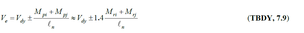
In this way, it is ensured that the power dissipation in the beam occurs with the ductile bending moment power depletion, instead of the brittle shear force power consumption. M pi and M pj are the positive or negative moment strength values calculated by considering the characteristic strength f ck of the concrete , the characteristic strength f yk of the reinforcement and the strength increase of the reinforcement , which are formed by taking into account the moment direction at the beam ends .
The moments M ri and M rj are the bearing strength moments calculated using the design strength f cd = f ck /1.5 of the concrete and the design yield stress of the reinforcement f yd = f yk /1.15. These values are the design strength values calculated with the Design Based on Strength approach.
The design strengths M ri and M rj values calculated from the Design Based on Strength approach, since the design strength f cd of the concrete and the design yield stress f yd of the reinforcement are used, the moment capacities at both ends are M pi = 1.4 M ri and M pj according to Article 7.4.5.1 of TBDY. = 1.4 M rj .
In this equation, V dy means the shear force due to vertical loads. For each loading combination, V dy consisting of vertical loads is calculated and the shear force resulting from earthquake loads is considered as the shear forces resulting from plasticization.
After finding the capacity moments M pi and M pj , using TBDY Equation 7.9, the shear force values on the ends of the beam can be found. TBDY Figure 7.9 shows the free body diagram of shear forces at beam ends due to capacitance moments.
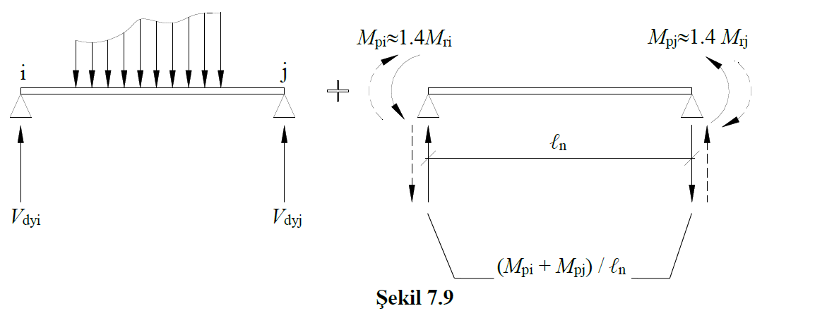
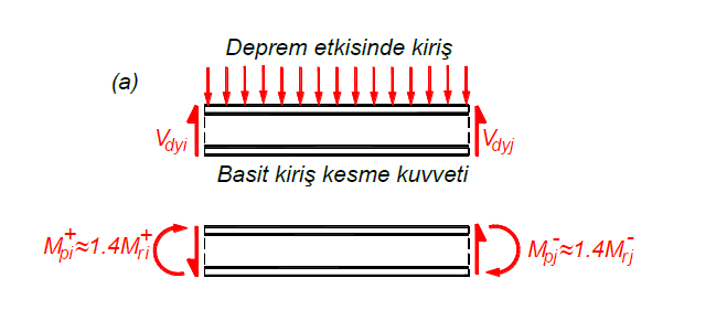
As can be seen in this figure, the direction of the plastic moments formed by the moment capacities in the beam changes according to the earthquake direction. For example, if the earthquake is acting in the + X direction, the shear forces consisting of the vertical loads and the moment capacities are as shown in the beam shown in the free body diagram in the picture below.
In this case, for the earthquake that will act in the -X direction, shear forces consisting of moment capacities together with the vertical loads are as shown in the beam shown in the free body diagram in the picture below.
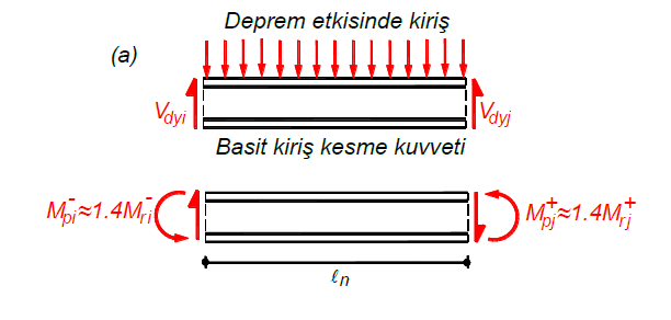
As can be seen, with the change in the direction of the earthquake, the plasticization that occurs in the beams will change, so the shear forces at the beam ends will also change due to this situation.
If the shear force calculated from the earthquake effects increased with the Resistance Excess Coefficient D together with the vertical loads, if the shear force calculated by TBDY Equation 7.9 is less than V e , the design shear force of the beam element is considered as this shear force.
It will continue from the example above, on the left side of the beam , the shear force value calculated by TBDY Equation 7.9 due to earthquakes in the + X direction and the vertical loads and the earthquake effects calculated with the Resistance Excess Coefficient D (for an earthquake in the + X direction) are compared and the shear force values calculated in the + X direction. The shear force V e to be used in the reinforcement calculation is found. This applies equally to the earthquake in the -X direction and to the left and right ends of the beams. Finally, the largest of the left and right internal shear force values is used as the basic shear force V e for the reinforcement design .
The shear force value to be taken as basis in the stirrup reinforcement calculation of the beam element is found by making the above comparison separately for the left end and right end. Shear force higher than the shear force used for stirrup design is used at the left and right ends. This account is calculated in all loading combinations and the most unfavorable condition is applied.
The limit values of the shear force are shown in TBDY Equation 7.10 in order to prevent the brittle power depletion caused by the oblique compressive stresses caused by the shear force in the beam .

In this equation b w is the body width of the beam and d is the useful height of the beam. f ck is the characteristic cylinder compressive strength of concrete.
V r is the shear strength of the beam section. It is calculated with the following steps according to TS500 .


At the same time , the upper limit of the shear force considered to prevent brittle fracture given in TS500 Equation 8.7 is also controlled. However , the control in TS500 Equation 8.7 is performed in loading combinations (1.4G + 1.6Q) without earthquake load.
The control in TBDY Equation 7.10 is made for all loading combinations that include earthquake load . However, TS500 Equation 8.7 is used as the upper limit of the shear force, which does not contain earthquake load and to prevent brittle failure .
Next Topic