
Steel Beam Design Settings are explained in detail under this title. After completing the steel beam modeling, double-click on the element to enter its properties. Two new sub-tabs, Releases / Partial Fixity” and “Design,” appear in the steel beam menu. These tabs contain adjustments for analysis and design.
Releases / Partial Fixity
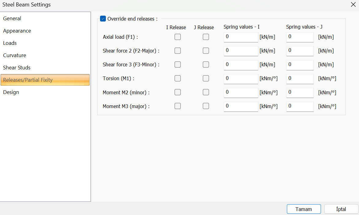
In the Releases tab, end releases and spring values are entered at the starting and ending points of the element.
|
Override end releases This command is activated by defining user-defined end releases. |
|
I-Release 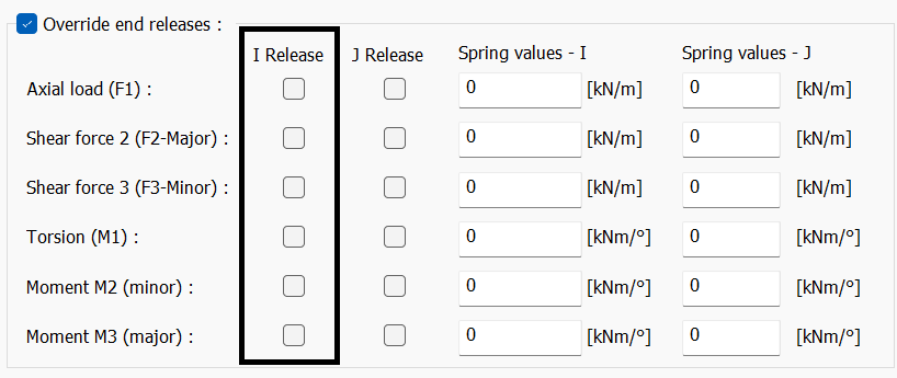
If the axial force for the starting point of the element 2-direction shear force, 3-direction shear force, torsion, 2-direction moment, and 3-direction moment are indicated, the corresponding force will be 0 at the starting point. |
|
J-Release 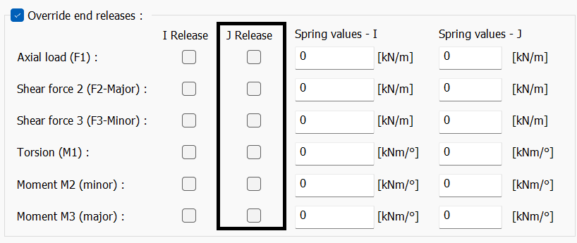
For the endpoint of the element, axial force, 2-direction shear force, 3-direction shear force, torsion, 2-direction moment, and 3-direction moment are indicated, and the corresponding force will be 0 at the starting end. |
|
Spring values - I 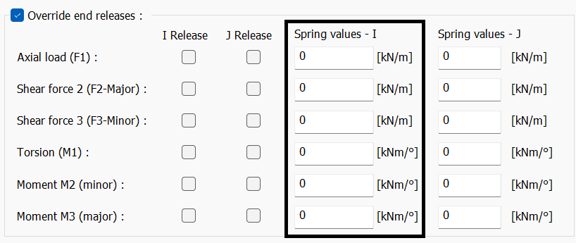
The spring coefficient is entered for the starting point of the element. Units can be changed by clicking the right button in the box. |
|
Spring values - J 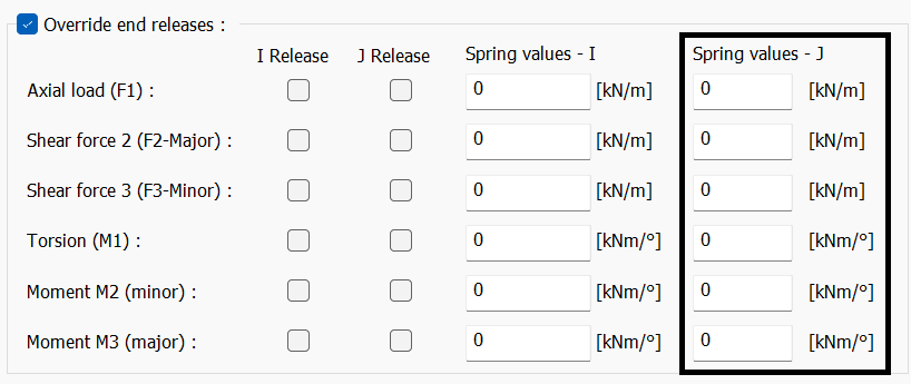
The spring coefficient is entered for the endpoint of the element. Units can be changed by clicking the right button in the box. |
Design
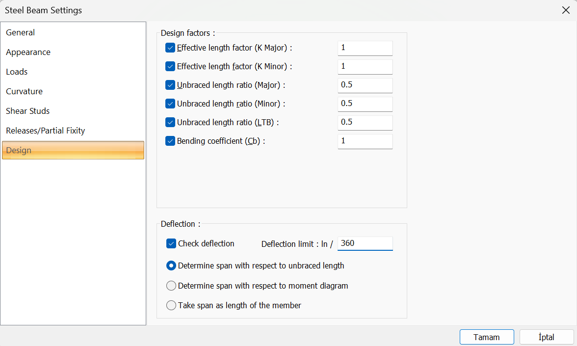
The parameters used in the design are intervened in the Design tab. If a mark is placed in the box, the coefficient written in the box is used in the design. If no mark is placed in the box, the ideCAD Structural automatically determines these coefficients and uses them in the design.
|
Effective length factor (K Major) Effective length factor for major axis. |
|
Effective length factor (K Minor) Effective length factor for minor axis |
|
Unbraced length ratio (Major) The ratio of the length between two elements connected to the element in its strong direction to the entire element length |
|
Unbraced length ratio (Minor) The ratio of the length between two elements connected in the weak direction to the entire element length |
|
Unbraced length ratio (LTB) The ratio of the length between laterally unbraced length along either flange |
|
Bending Coefficient (Cb) Lateral-torsional buckling modification factor for nonuniform moment diagrams when both segment ends are braced. It’s determined according to AISC 360-16 F1-1. |
|
Check deflection/Deflection limit:ln It is the member-based limit value specified in the relevant Steel Structures regulation used in the design. The program does not defıne automatically type of the structural member, such as cantilever beams. The limit value must be changed by the user according to the situations where the beam is used. |
|
Determine span with respect to unbraced length The length between the two members to which the relevant member is attached or placed uses the clear distance in deflection calculation. It is preferred in hinged connections. |
|
Determine span with respect to moment diagram The equation used in deflection calculation changes according to the shape of the moment diagram of the relevant member. For this reason, cantilever beams should be used in beams with one side is fixed and the other one is hinged. |
|
Take span as length of the member It provides deflection calculation over the full length of the relevant element. |
-
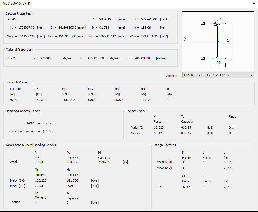
After analysis and design, the design check window is given in the “steel design → beam details” section.
Next Topic