
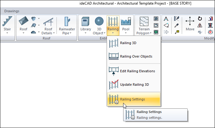
With the Railing Settings command, railing elevation, type, material, rails, posts and plate settings can be accessed.
Location of the Railing Settings Command
You can access it under the Ribbon menu Home tab, Entities title.
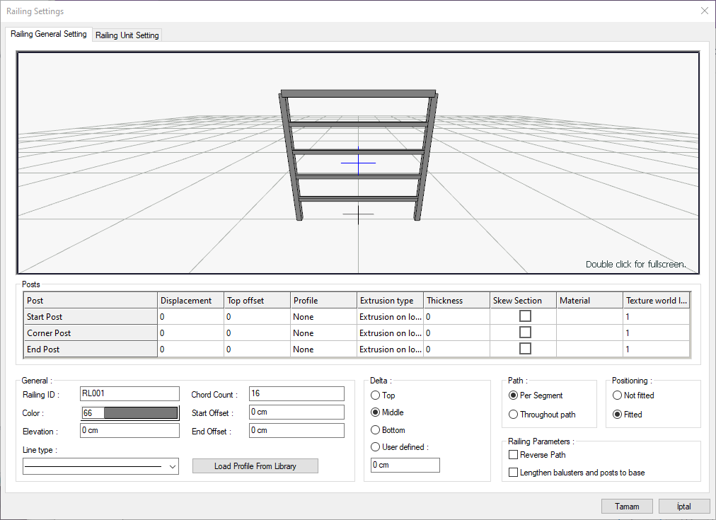
Railing General Settings Tab
|
Specifications |
|---|
|
Railing preview 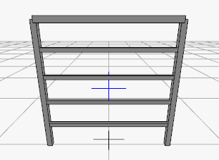
It is the 3 dimensional view of the railing object being worked on. You can rotate the image around itself by holding down the left mouse button and moving it. You can zoom in and out by holding the right mouse button and moving the mouse. |
|
Post 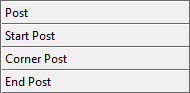
The start post is the vertical profile placed at the first point of the railing object.
|
|
Displacement 
Sets the distance of the post from the railing object. The perpendicular is shifted left and right according to the negative and positive value. |
|
Top offset 
This column, which becomes functional when the extrusion type Z direction is selected in the table on the right, determines how much the strut element will extend or shorten from the top. A positive value means that it will grow from the top, and a negative value means it will shorten. |
|
Profile 
It is the column that determines the section of the strut object. A suitable profile is selected from the list. |
|
Extrusion type 
It is the column that determines the method by which the 3D profile will be extended. Extrusion on local z: This method is a method that enables a profile to be obtained by extending a section defined as 2B in the horizontal plane in the direction of the z local axis.
|
|
Thickness 
The thickness of the profile element whose extension type is x or y direction is given in this column. |
|
Material 
The material to be used for the relevant profile is selected from the list. |
|
Texture world length 
The texture length of the material used is entered. For example; If 1 is entered, the selected material texture width is taken as 1 unit and covered on the relevant walls. Considering that the texture is in the form of a square, the object surfaces are covered with 1x1 textures arranged side by side. It can be determined separately for each surface. |
|
Railing ID The program will give a name to the railings by default. The name of the railing can be seen on this line, another name can be given if desired. |
|
Color The color of the railings is selected from the color palette that opens when clicked. |
|
Line type The line type of the railing object is selected from the list that opens when clicked. |
|
Elevation It is the elevation value of the railing object according to the floor base. Depending on the negative or positive value, the guardrail is shifted up or down. |
|
Chord count It determines the number of sides of the vertical profiles created by the rotated object method in railing and pillars. The greater value allows a denser circle. The default value is fine. |
|
Start offset Offsets the starting post by the entered value. |
|
End offset Offsets the end post by the entered value. |
|
Load profile from library It calls the profile types previously prepared and saved to disk or project to the project. |
|
Delta 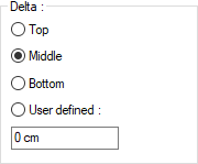
The railing point is chosen. One of the top, middle, bottom and user defined options is selected. |
|
Path 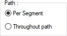
In the process of placing the railing object, the placement is the option that regulates whether it will be along the throughout path (entire line) or along each per segment (line segment). If the throughout path is selected, the method specified as the settlement method is applied for the entire path. If the per segment is selected, the method chosen is applied at each of the spacers. |
|
Positioning 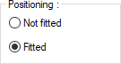
In the placement process of the railing object, it is the option that determines whether the placement will be made by fitting along the path or by allowing it to remain at the end. When fit is selected, guardrail profiles are created to be evenly distributed along the road, regardless of spacing. If the Fit option is checked, each railing profile will be created with the distances defined for it and the distance left at the end. |
|
Reverse path This option takes the symmetry of the railing relative to its own plane. |
|
Lengthen balusters and posts to base It performs the automatic extension of the vertical rails and posts to a certain base on the railings that are drawn on object basis and given the elevation value. This process allows the railing posts to be extended over the landing, especially in the elevation differences from the curved part to the landing part on the stairs. |
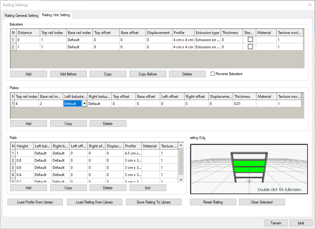
Railing Unit Settings
|
Specifications |
|---|
|
Balusters 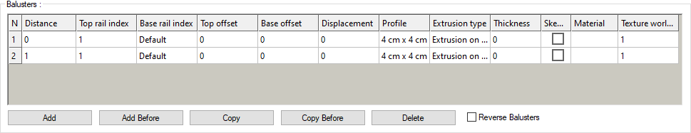
The baluster is made in this table. Each baluster profile is defined as one row in the table. |
|
Plates 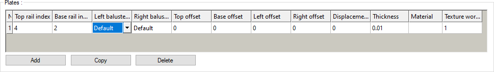
The plates between the balusters and rails are defined with the help of this table. |
|
Rails 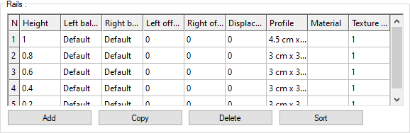
Rails are made in this table. Each rail profile is defined as one row in the table. |
|
Load profile from library It calls the profile types previously prepared and saved to the profile folder or project to the project. |
|
Load railing from library It calls the railing types previously prepared and saved in the railing folder or project to the project. |
|
Save railing to library It saves the prepared railing system in the railing folder. |
|
Reset railing Deletes all defined railing system by clearing the table |
|
Clear selected Any element selected in the table is displayed in a green color in the 3D image. This command removes that selection. |
|
Railing preview 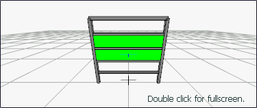
It is the 3 dimensional view of the railing object being worked on. You can rotate the image around itself by holding down the left mouse button and moving it. You can zoom in and out by holding the right mouse button and moving the mouse. |
Railing Profiles Section
|
Specifications |
|---|
|
N It is the number of balusters and will correspond to the row number in the table as defined. Baluster numbers are given starting from 1 from left to right. In the railing system defined accordingly, the first profile on the left will be the railing numbered 1. The number will increase to the right as you define it. |
|
Distance 
The distance between the two balusters profiles is given. |
|
Top rail index 
In this column, to which rail profile the balusters will be extended from the top or which rail profile will be cut from the top. The rail profiles defined in the table below are numbered in their own system. A rail profile number is selected in this column. Choosing the default instead of giving the number usually creates the system in a way that corresponds to each other. For the railing system other than that, an appropriate number indicating the index number of the relevant rail profile is selected. |
|
Base rail index 
In this column, to which rail profile the baluster will be extended from the bottom or in which rail profile it will be cut from below. The rail profiles defined in the table below are numbered in their own system. A rail profile number is selected in this column. Choosing the default instead of giving the number usually creates the system in a way that corresponds to each other. For the railing system other than that, an appropriate number indicating the index number of the relevant rail profile is selected. |
|
Top offset 
It determines how much the baluster profile will extend or shorten from the top. Positive value means longer, negative value means shorter. |
|
Base offset 
It determines how much the baluster profile will extend or shorten from the bottom. A positive value means lengthening, negative value means shortening. |
|
Displacement 
Adjusts the distance of the baluster profile from the system. According to the negative and positive value, the baluster profile is shifted further or backward. |
|
Profile 
It is the column that determines the section of the baluster profile. A suitable profile is selected from the list. |
|
Extrusion type 
It is the column that determines the method by which the 3D profile will be extended. Extrusion on local z: This method is a method that enables a profile to be obtained by extending a section defined as 2B in the horizontal plane in the direction of the z local axis.
|
|
Thickness 
The thickness of the profile element whose extension type is x or y direction is given in this column. |
|
Material 
The material to be used for the relevant profile is selected from the list. |
|
Texture world length 
The texture length of the material used is entered. For example; If 1 is entered, the width of the selected material texture is taken as 1 unit and covered on the relevant walls. Considering that the texture is in the form of a square, the object surfaces are covered with 1x1 textures arranged side by side. |
|
Add Adds a new baluster profile to the table. |
|
Add before Adds a new baluster profile above the row with the cursor in the table. |
|
Copy Adds a new balyster profile to the bottom by copying the values in the row with the cursor in the table. |
|
Copy before Adds a new baluster profile above the row where the cursor is, by copying the values in the row with the cursor in the table. |
|
Delete Deletes the profile in the row with the cursor in the table. |
|
Reverse balusters It takes the symmetry of the profile used in the vertical with respect to the axis passing through the middle. |
Plates
|
Specifications |
|---|
|
N It is the number of the plates and as you define it, it will correspond to the row number in the table. |
|
Top rail index In this column, the profile of the plate to be extended from the top to which rail profile or the profile of the rail to be cut from the top. The rail profiles defined in the table below are numbered in their own system. A rail profile number is selected in this column. Choosing the default instead of giving the number usually creates the system in a way that corresponds to each other. For the plate system other than this, a suitable number is selected indicating the index number of the relevant rail profile. |
|
Base rail index In this column, to which rail profile the plate will be extended from the bottom or in which rail profile it will be cut from below. The rail profiles defined in the table below are numbered in their own system. A rail profile number is selected in this column. Choosing the default instead of giving the number usually creates the system in a way that corresponds to each other. For the plate system other than this, a suitable number is selected indicating the index number of the relevant rail profile. |
|
Left baluster index To which baluster profile the plate will be extended from the left or in which baluster profile to be cut from the left is given in this column. The baluster defined in the table above are numbered in their own system. A baluster profile number is selected in this column. Choosing the default instead of giving the number usually creates the system in a way that corresponds to each other. For the plate system other than that, an appropriate number indicating the index number of the relevant baluster is selected. |
|
Right baluster index In this column, to which baluster the plate will be extended from the right or in which baluster to be cut from the right. The baluster defined in the table above are numbered in their own system. A baluster number is selected in this column. Choosing the default instead of giving the number usually creates the system in a way that corresponds to each other. For the plate system other than that, an appropriate number indicating the index number of the relevant baluster is selected. |
|
Top offset It determines how much the plate will extend or shorten from the top. Positive value means longer, negative value means shorter. |
|
Base offset It determines how long the plate will extend or shorten from the bottom. Positive value means longer, negative value means shorter. |
|
Left offset It determines how much the plate will extend or shorten from the left. Positive value means longer, negative value means shorter. |
|
Right offset It determines how much the plate will extend or shorten from the right. Positive value means longer, negative value means shorter. |
|
Displacement Adjusts the distance of the plate from the system. According to the negative and positive value, the plate is shifted further or back. |
|
Thickness The thickness of the profile element whose extension type is x or y direction is given in this column. |
|
Material The material to be used for the relevant profile is selected from the list. |
|
Texture world length The tissue length of the material used is entered. For example; If 1 is entered, the width of the selected material texture is taken as 1 unit and covered on the relevant walls. Considering that the texture is in the form of a square, the object surfaces are covered with 1x1 textures arranged side by side. |
|
Add Adds a new plate to the table. |
|
Copy Adds a new plate to the bottom by copying the values in the row with the cursor in the table. |
|
Delete Deletes the plate in the row with the cursor in the table. |
Rails Section
|
Specifications |
|---|
|
N It is the number of the rail profiles, and it will correspond to a row number in the table as you define it. Rail profile numbers are given starting from 1 from top to bottom. In the rail system defined accordingly, the first row at the top will be the rail profile no.1. As you define it, the correct number will increase to the bottom. |
|
Height 
It is the elevation value of the rail profile with respect to the base. The top rail has the highest elevation value and is in row 1. |
|
Left baluster index 
To which baluster the rail profile will be extended from the left or in which baluster to be cut on the left is given in this column. The balusters defined in the table above in the dialog are already numbered in their own system. A baluster profile number is selected in this column. Choosing the default instead of giving a number usually creates the system in a way that corresponds to each other. For the rail system to be defined, a suitable number indicating the index number of the relevant baluster is selected from the list. |
|
Right baluster index 
To which baluster the rail profile will be extended from the right or in which baluster to be cut on the right is given in this column. The balusters defined in the table above in the dialog are already numbered in their own system. A baluster profile number is selected in this column. Choosing the default instead of giving a number usually creates the system in a way that corresponds to each other. For the rail system to be defined, an appropriate number indicating the relevant baluster index number is selected from the list. |
|
Stretch left 
It determines how far the rail profile will extend to the left or how much shorter it will be from the left. Positive value means longer, negative value means shorter. |
|
Stretch right 
It determines how far the rail profile will extend to the right or how much shorter it will get from the right. Positive value means longer, negative value means shorter. |
|
Offset 
Adjusts the distance of the rail profile from the system. According to the negative and positive value, the handrail profile is shifted further or backward. |
|
Profile 
It is the column that determines the section of the rail profile. A suitable profile is selected from the list. |
|
Material 
The material to be used for the relevant profile is selected from the list. |
|
Texture world length 
The tissue length of the material used is entered. For example; If 1 is entered, the width of the selected material texture is taken as 1 unit and covered on the relevant walls. Considering that the texture is in the form of a square, the object surfaces are covered with 1x1 textures arranged side by side. |
|
Add Adds a new rail profile to the bottom of the table. |
|
Copy Adds a new rail profile at the bottom by copying the values in the row with the cursor in the table. |
|
Delete Deletes the rail profile in the row with the cursor in the table. |
|
Sort It lists the defined rail profiles to be numbered from top to bottom according to the given height values. |
Next Topic