
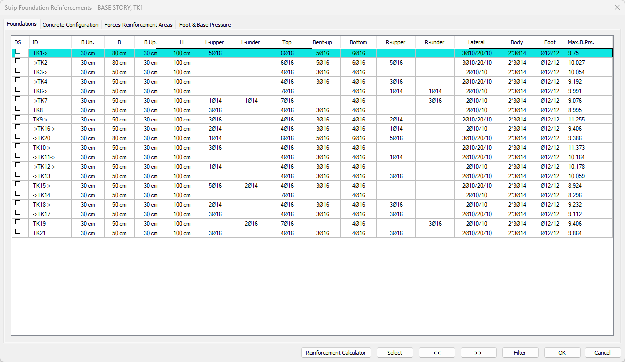
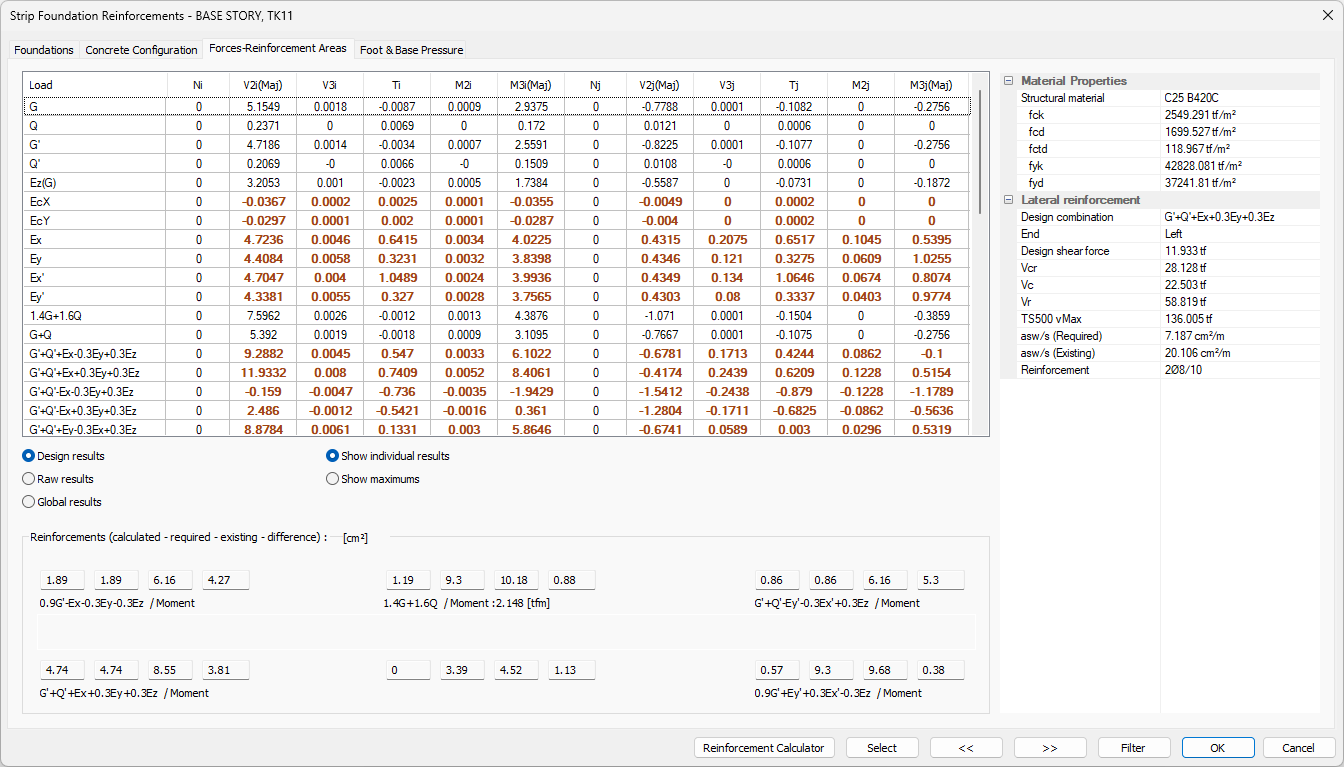
Strip foundation reinforcement design results and inadequacy of strip foundations are displayed in the Strip Foundation Reinforcement dialog. In the Strip Foundation Reinforcement dialog, the results of foundation reinforcements, internal forces and ampatment-base pressure are given.
Location of Strip Foundation Reinforcements Dialog
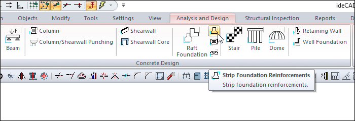
After the analysis, you can access it by clicking the Strip Foundation Reinforcements command under the Concrete Design title of the ribbon menu Analysis and Design tab .
General Specifications of Strip Foundation Reinforcements Dialogue
|
Summary Information The summary information about the line where the cursor is located is given in the form of Story Name, in the name section of the dialog. 
For example Base Story, TK25 |
|
Using the Shift key In this tab, you can select more than one row with the Shift key, enter a value by double-clicking any cell whose value is open to change, and you can make that value apply to all selected rows. |
|
Using the Ctrl key Ctrl key, on the other hand, selects the lines in between one by one. |
|
Reinforcement calculator Calculates the amount of rebar, in area, for the selected diameter and span. |
|
Select Selects the object on the line with the cursor. When the concrete dialog is closed, you can take action for the selected element. |
|
Previous The cursor moves to the previous line. |
|
Next The cursor goes to the next line. |
|
Filter It is used to define certain conditions and filter only the elements that satisfy that condition. |
|
Ok It saves the changes made and closes the dialog. |
|
Cancel Closes the dialog without saving the changes made. |
Insufficiency Code Description and Recommended Solution
|
Insufficiency Code |
Description |
|---|---|
|
K |
Shear safety is not satisfied.
|
|
M |
The maximum reinforcement ratio is exceeded.
|
|
Zg |
Soil bearing capacity is exceeded.
|
|
As(-) |
Provided reinforcement area is insufficient.
|
Foundations Tab
|
Specifications |
|---|
|
DS It is the rebar fixing column. If marked, the rebars are fixed. When changes are made to the foundation rebar , DS is automatically marked and the rebar remains constant even if the analysis is made. If the DS is not marked, the rebars are determined again after the analysis according to the rebar selection conditions. |
|
ID 
It is the name of the foundation in the plan. (TK1, TK101, TK10 etc.) In case of negativity, the term related to negativity is added next to the name. Like TK101 (Zg). |
|
B un. 
It is strip the width of the underlying foot with respect to the direction of view. |
|
B 
It is the width of the strip foundation beam. |
|
B up 
Strip foundation is the width of the foot on top according to the viewing direction. |
|
H 
It is strip foundation height. |
|
L-upper 
It is the value in terms of number and diameter of the rebar located on the left support section of the foundation beam. You can make changes by double-clicking the cell. |
|
L-under 
It is the value in terms of number and diameter of the rebar located under the left support section of the foundation beam. You can make changes by double clicking the cell. |
|
Top 
It is the value of flat rebar of the foundation beam in units and diameter. |
|
Bent-up 
It is the value of the pleated rebar of the foundation beam in terms of number and diameter. You can make changes by double clicking the cell. |
|
Bottom 
It is the value of the mounting rebar of the foundation beam in terms of number and diameter. You can make changes by double clicking the cell. |
|
R-upper 
It is the value in terms of number and diameter of the rebar located on the right support section of the foundation beam. You can make changes by double clicking the cell. |
|
R-under 
It is the value in terms of number and diameter of the rebar under the right support section of the foundation beam. You can make changes by double clicking the cell. |
|
Lateral 
It is the diameter and spacing of the strip foundatin in the middle zone and densification zone, respectively. You can make changes by double clicking the cell. |
|
Body 
It is the value of the strip foundation rebar in terms of number and diameter. You can make changes by double clicking the cell. |
|
Foot 
It is the value of foot rebar in terms of diameter and range. |
|
Max.B.Prs. 
It is the maximum base pressure available from a combination of fixed, mobile and horizontal loading. |
Concrete Configuration Tab
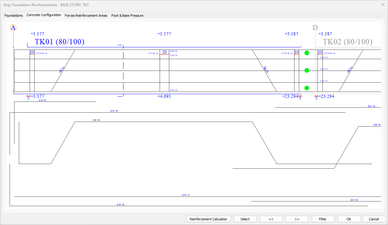
You can shift the drawing left and right by holding down the left mouse button. When you click on the beam text indicating the name of the beam (K1 25/50 etc), a dialog appears showing the rebar selected as a result of the beam concrete. Diameter and / or quantity of rebar can be changed in this dialog. If desired, any rebar text value can be clicked. In this case, a dialog opens where the clicked rebar text value can be changed.
In the concrete configuration, especially the green and / or red circles that appear on the supports of continuous beams determine where the beam rebars are to be cut. If the circle is green, the rebar is continued to the next span (If the maximum length of the rebar is sufficient. This value is default 12 meters. It can be changed in the Project General Settings dialog). If the circle is red, the rebar is cut at the support. Circles are turned into red and / or green (rebar passes / does not pass) by clicking with the mouse. According to the rebar cutting status, the rebar arrangement is made automatically, excess or missing rebars can be monitored on the screen. Missing rebars are transmitted to the user in red.
Forces - Reinforcement Areas Tab
|
Specifications |
|---|
|
Table of forces 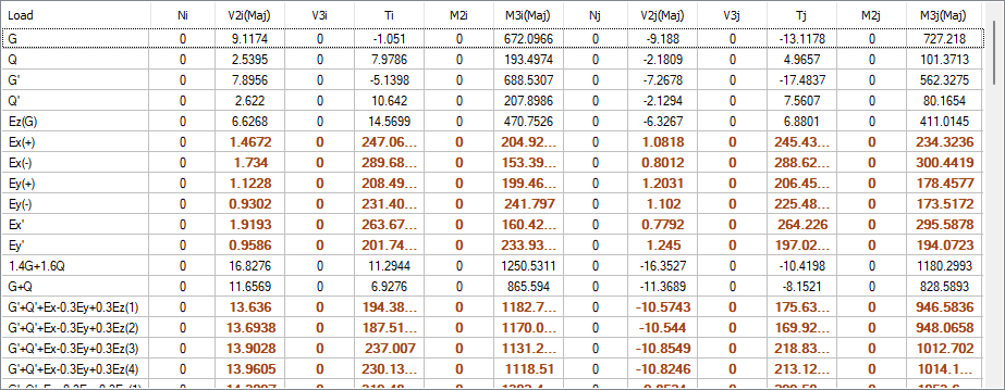
Load: The name of the respective load or load combinations.
|
|
Design results After the analysis, the regulation conditions have been applied, therefore it shows the end forces that have undergone changes and going to the design. In addition, the values used are shown in bold. End forces are values calculated on the element local axes. |
|
Raw results After analysis, it shows the raw end forces that are not applied to the regulation conditions. End forces are effects on the element local axes. |
|
Global results After the analysis, these are the values in global coordinates of the extreme forces that are not applied regulation conditions. |
|
Show individual results For 4 modal analysis cases, 4 different results are obtained from each earthquake loaded combination. If you want the program to display the values obtained for each modal state one by one, you should check this option. |
|
Show maximums The biggest values of 4 different results obtained from each load combination for 4 different modal cases are shown in the table. |
|
Reinforcements (calculated - required - existing - difference) 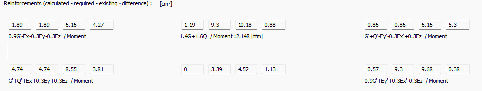
At the left support of the foundation beam, upper and lower; in the middle; clearance and mounting; in the right bracket; The sum of the calculated-required-existingdifference reinforcement areas is given as top and bottom. Just below, the loading combination of the reinforcement calculation and the moment values of that combination are also written. |
|
Material properties 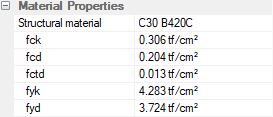
Structural material: The structural material of the strip foundation.
|
|
Lateral reinforcement 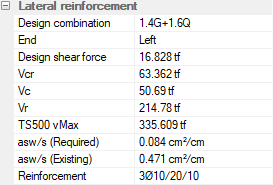
Design combination: The name of the load combination that gives the Vd value.
|
Foot and Base Pressure Tab
|
Specifications |
|---|
|
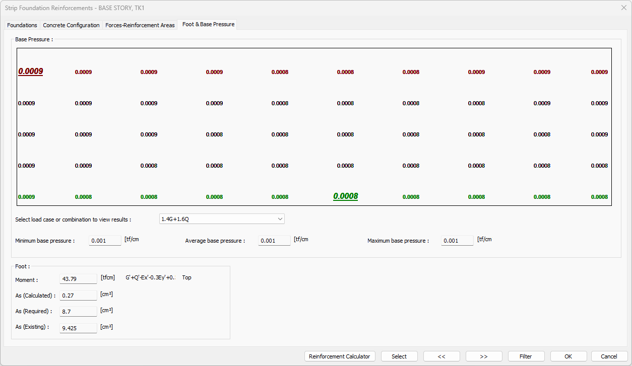
Pressure values and loading combination 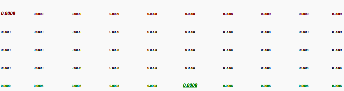
All pressure values are listed, from maximum pressure to minimum pressure, depending on the choice of loading combination. |
|
Select load case or combination to view results The combination in which the pressure values are shown is selected. |
|
Minimum / Average / Maximum base pressure Minimum base pressure: It is the minimum base pressure value consisting of all loads.
|
|
Foot 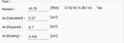
Moment: It is the moment value used in foot concrete calculation.
|
Next Topic
Related Topics