
Symbols
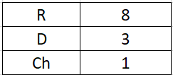
D = Excess of strength coefficient
R = Coefficient of behavior of the carrier system
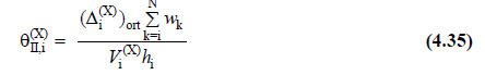
θII,i (X) = (X) second order indicator value defined for each i'th floor in the earthquake direction
θII,max (X) = (X) defined in the earthquake direction maximum second order indicator value
Vi(X) = (X) reduced storey shear force at ith floor in earthquake direction [kN]
hi = height of ith floor [m]
∆i,avg (X) = (X) average reduced relative story drift [m]
wk = total weight acting on the kth story [kN]
βII (X) = Second order amplification coefficient
βtE (X) = Equivalent base shear force amplification coefficient
-
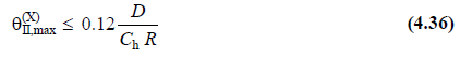
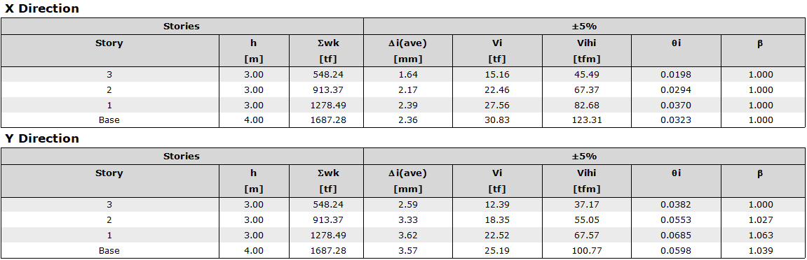
For each direction, the second order indicator value θII,i is determined automatically according to TBDY 4.9.2 for all stories. If maximum θ II,max satisfies the condition given below; second-order effect is not taken into consideration to determine the internal forces based on design.
-
Ch is a coefficient determined depending on the non-linear hysteretic behavior of the structural system and is taken as 1 for steel structures as per TBDY 2018 4.9.2.2.
-
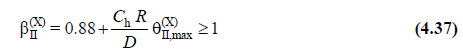
If the condition given in Equation 4.36 is not satisfied , the internal forces obtained from the horizontal earthquake effects are increased with the βII coefficient determined by the equation below .
-
This value calculated for all stories is used only to increase the internal forces of the upper section elements as per TBDY 4.9.2.4.
-
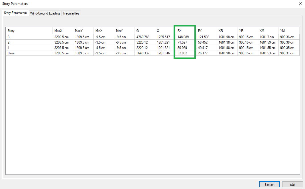
For manual check, Vi and wk values are obtained from Story Parameters section in Analysis and Design tab of the program.
-
From the table above, the X-direction floor forces, Vi, for FX; FY columns are used for the Y direction storey forces. Since the values in the FX column are only the force acting on the relevant floor, they are added down and the total shear force diagram for the building is generated. The values given in the column Vi in the table below are obtained in this way.
-
wk is for the total weight affecting the floor, and the values in the G and Q columns from the table above are combined to be G+0.3Q. Here, 0.3 is live load participation factor and it is chosen as 0.3 for this building.
-
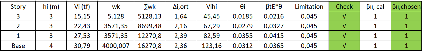
Average storey displacement values are used directly as values in the program report. Equation 4.36 is used for limit value calculation. The values of the building used in the calculation are as follows:
-
The result of the calculation for the building is given in the earthquake regulation report.
-
According to βII =1 for the building, there is no increase. If it is greater than 1, it should be increased the stiffness.
-
The excel table for the manual part of the check can be obtained here.