
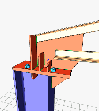
With the Seating Truss Connection command, column-truss connection is defined.
Location of the Seating Truss Connection Command
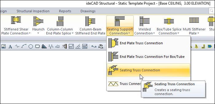
You can access it under the Ribbon menu, Connection tab, Experimenetals title.
Usage Steps
-
From the connection menu, click on the Seating Truss Connection icon.
-
Select the column before the 3D perspective view and click the right mouse button.
-
Then select the truss elements attached to the column and click the right mouse button.
-
The connection will be created with default settings.
Location of the Seating Truss Connection Dialog
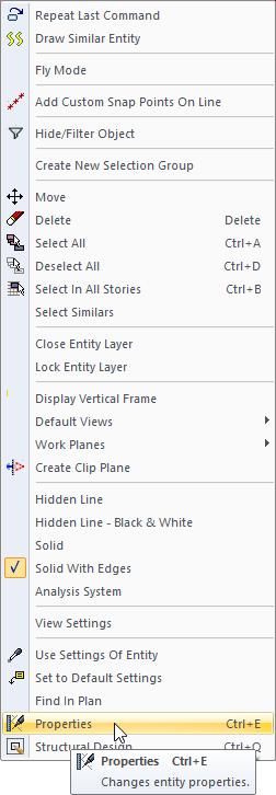
Select the connection and click the right mouse button. Click the Properties line from the right click menu that opens.
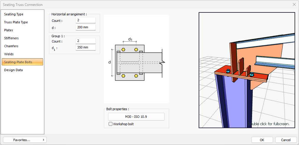
Seating Truss Connection Dialog
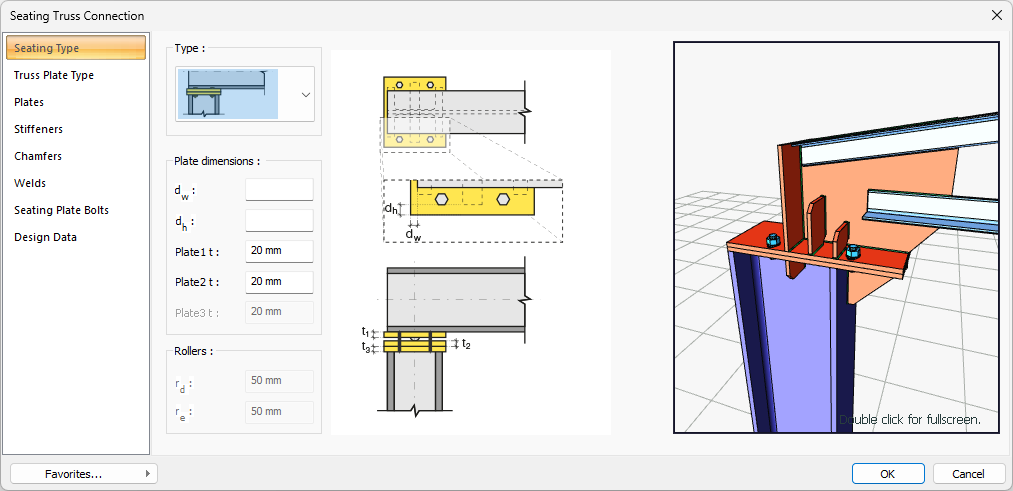
Seating Type Tab
|
Specifications |
|---|
|
Type 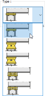
One of the connection types is selected from the list. |
|
Plate dimensions 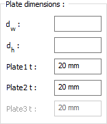
Plate dimensions are determined by entering values. The values to be entered are shown in the schematic drawing. |
|
Rollers 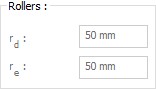
Roller sizes are determined by entering values. |
|
Schematic drawing 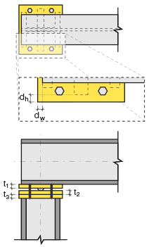
Connection and plate values are shown on the schematic drawing. |
|
Preview 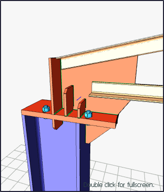
There is a preview of the connection. The selection made and the entered values can be followed simultaneously in the preview. |
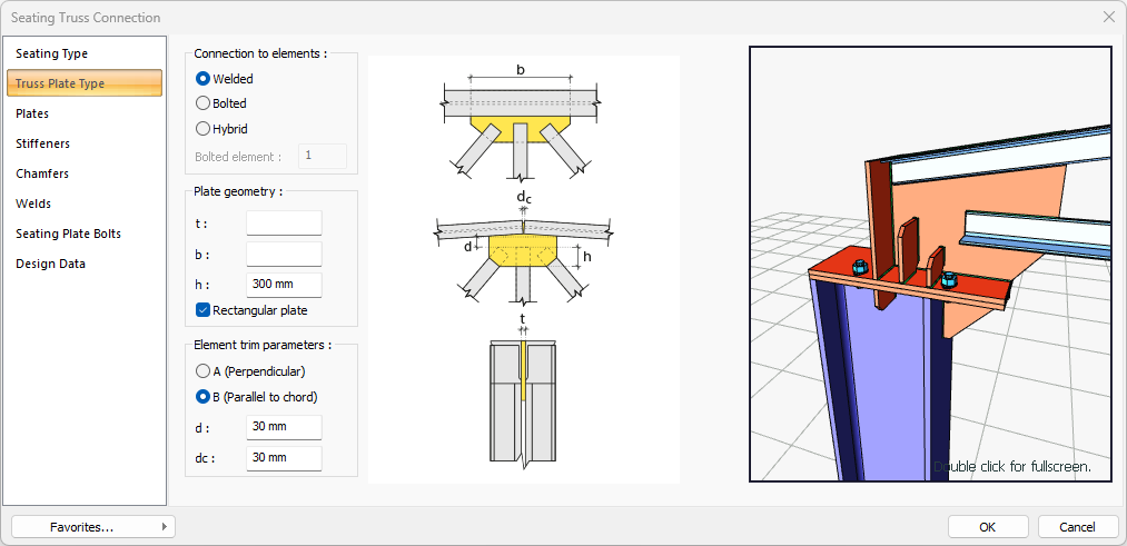
Truss Plate Type
|
Specifications |
|---|
|
Connection to elements 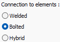
Welded, bolted or hybrid connection type is selected for combination. |
|
Bolted element Become active when hybrid option is selected. The element to be bolted is determined. |
|
Plate geometry 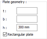
Plate dimensions are determined by entering values. The values to be entered are shown in the schematic drawing. |
|
Element trim parameters 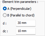
Element trim type options are given. Also element trim parameters are determined by entering values. The values to be entered are shown in the schematic drawing. dc settings is just for truss top connection. Adjusts the distance between top elements. |
|
Schematic drawing 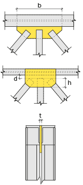
Connection and placement values are shown on the schematic drawing. |
|
Preview
There is a preview of the connection. The selection made and the entered values can be followed simultaneously in the preview. |
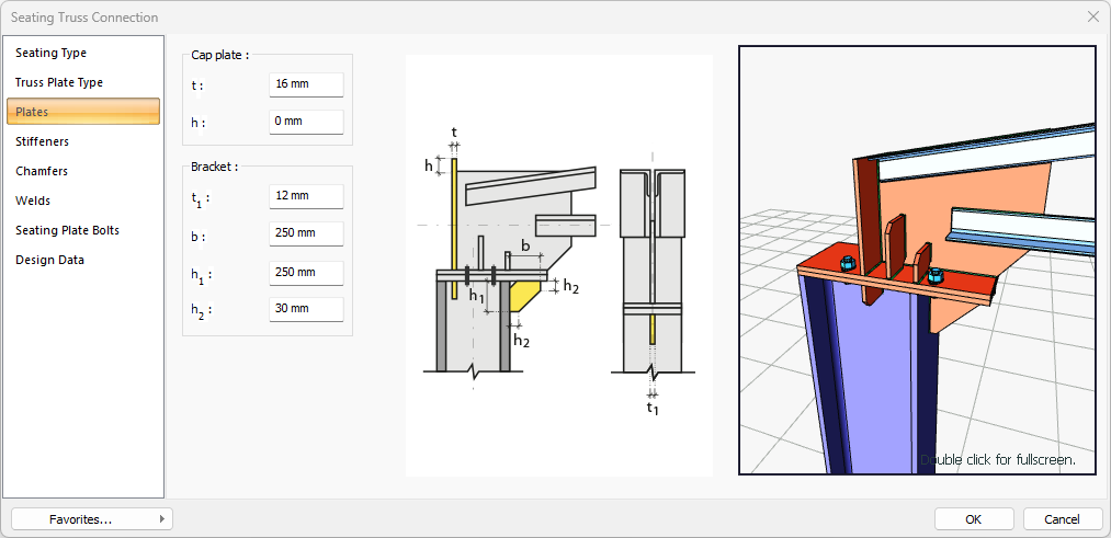
Plates Tab
|
Specifications |
|---|
|
Cap plate 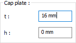
The cap plate is determined by entering the value. The values to be entered are shown in the schematic drawing. |
|
Schematic drawing 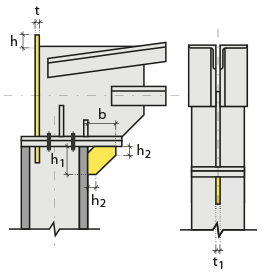
Connection and plate values are shown on the schematic drawing. |
|
Preview
There is a preview of the connection. The selection made and the entered values can be followed simultaneously in the preview. |
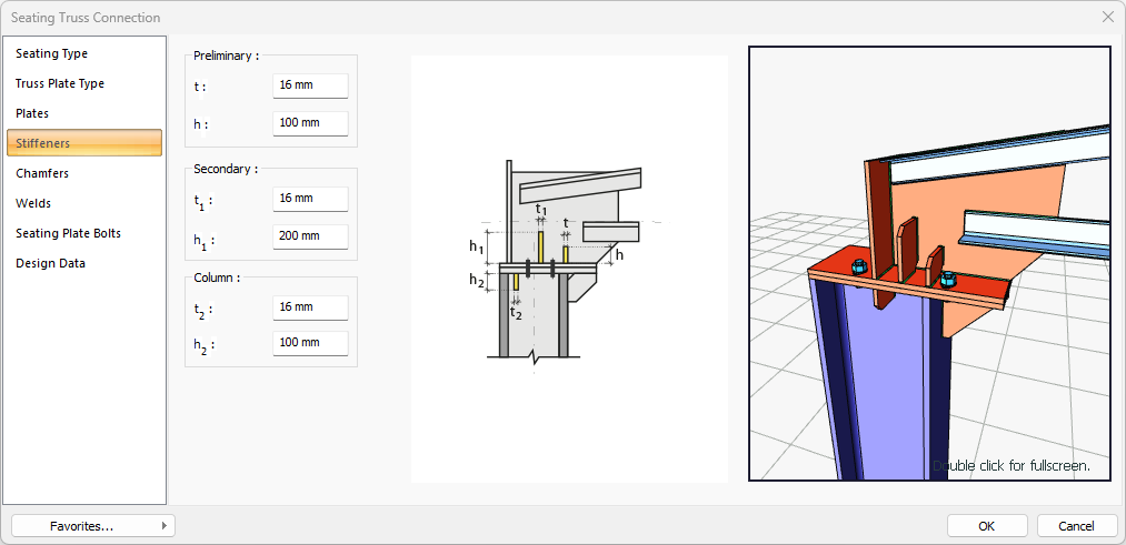
Stiffeners Tab
|
Specifications |
|---|
|
Preliminary 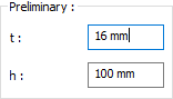
The preliminary plate is determined by entering the values. The values to be entered are shown in the schematic drawing. |
|
Secondary 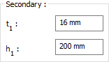
Secondary plate is determined by entering the values. The values to be entered are shown in the schematic drawing. |
|
Column 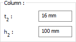
The column is determined by entering the values. The values to be entered are shown in the schematic drawing. |
|
Schematic drawing 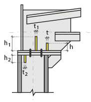
Connection and plate values are shown on the schematic drawing. |
|
Preview
There is a preview of the connection. The selection made and the entered values can be followed simultaneously in the preview. |
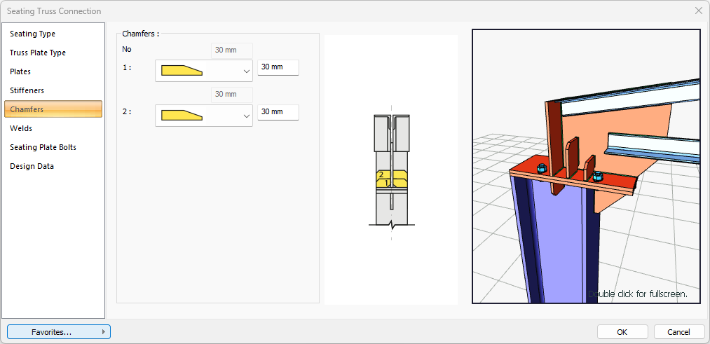
Chamfers Tab
|
Specifications |
|---|
|
Chamfers 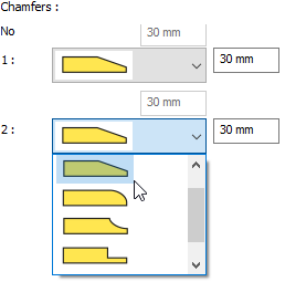
The use of slope, slope type and geometric properties are determined by entering the value for easy assembly of the plates in the field. |
|
Schematic drawing 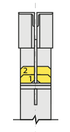
Connection, notching and cutting values are shown on the schematic drawing. |
|
Preview
There is a preview of the connection. The selection made and the entered values can be followed simultaneously in the preview. |
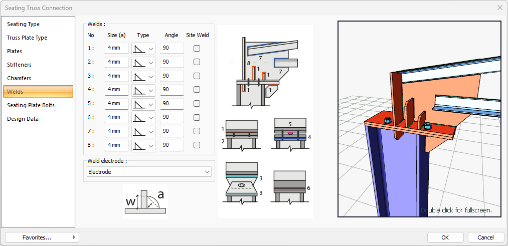
Welds Tab
|
Specifications |
|---|
|
Welds 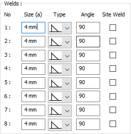
The thickness, type and angle values of the welds to be made at the connections are given. The information on whether it will be done on the construction site or not is entered. |
|
Weld electrode The strengths of the welding electrodes are defined in the design inputs. The strength of the main element in the weld joint is controlled under the condition that it has less strength than the weld strength. If necessary, click the list and define "Create New…". To create the welding electrode, give the information "Name" and "Weld metal tensile strength" in the dialog that opens after clicking "Create New". Welding geometry is determined automatically by the program. These properties can be changed to easily determine the connection properties. Geometry features are in accordance with industry standards and in the form specified in AISC. 
|
|
Schematic drawing 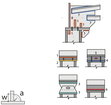
Connection and weld values are shown on the schematic drawing. |
|
Preview
There is a preview of the connection. The selection made and the entered values can be followed simultaneously in the preview. |
Seating Plate Bolts Tab
|
Specifications |
|---|
|
Horizontal arrangement 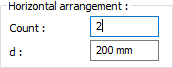
The horizontal arrangement distance value of the bolts is entered. The values to be entered are shown in the schematic drawing. |
|
Group 1 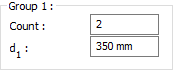
Distance values of bolts to beam and other bolts are entered. The values to be entered are shown in the schematic drawing. |
|
Bolt properties 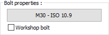
The Hole and Bolt Parameters dialog is opened by clicking on the bolt properties button. The bolt properties are set in this dialog. |
|
Schematic drawing 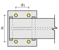
Connection and bolt placement values are shown on the schematic drawing. |
|
Preview
There is a preview of the connection. The selection made and the entered values can be followed simultaneously in the preview. |
Design Inputs Tab
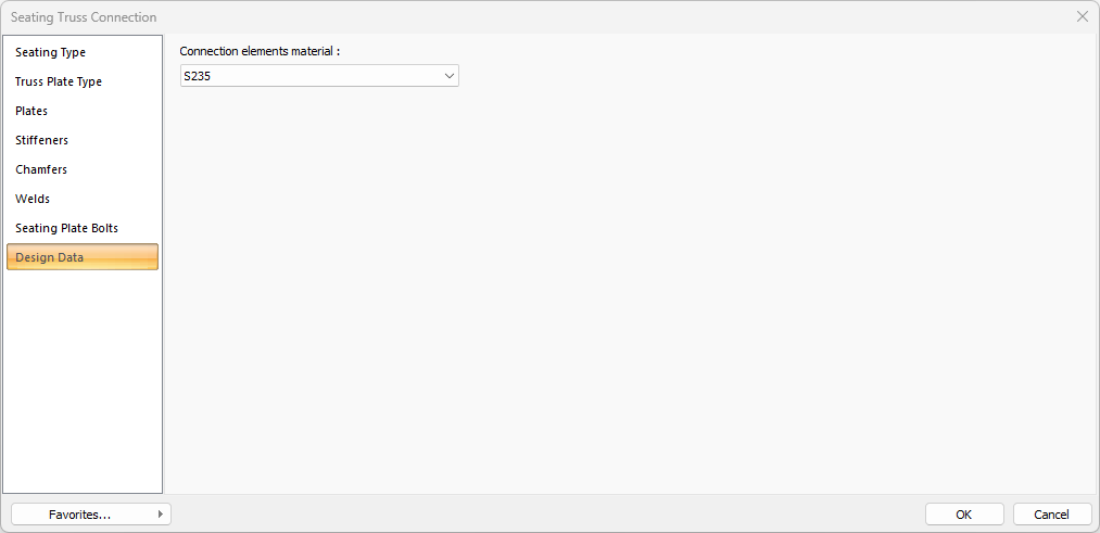
In the design data, the connection elements material is defined. The condition that the main element in the weld joint has less strength than the weld strength is controlled.
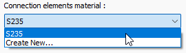
If necessary, click the list and define "Create New…". To create the connection elements material, give the information material definitions and values in the dialog that opens after clicking "Create New".
Next Topic