
ICONS
A s1 = Total area of the tensile reinforcement placed on one side of the column-beam node to accommodate the negative moment of the beam
A s2 = The total area of the tensile reinforcement placed on the other side of thecolumn-beam node with respect to A s1 to accommodate the positive moment of the beam
b j = In the earthquake direction considered, if the beam stuck in the joint area is the same width as the column or protrudes from both sides of the column, the column width, otherwise, twice the distance from the vertical middle axis of the beam to the column edges (the beam width cannot exceed the sum of the height of the junction)
b w = beam width of the body
f ck = concrete characteristic cylindrical compressive strength
f yk = resistance to flow characteristic of longitudinal reinforcement
h = cross section dimension in the earthquake direction Considering the Column
V e = column, beam, combination of and taken as a basis shear of transverse reinforcement accounts curtain
V Arm = The smaller of the column shear forces calculated according to Section 4 above and below the node point
ϕ = Reinforcement diameter
7.5. COLUMN JOINTS IN FRAME SYSTEMS OF HIGH DUCTILITY LEVEL
7.5.1. Confined and Unconfined Joints
Column-beam joints in frame systems consisting of columns and beams of high ductility level will be divided into two classes as described in (a) and (b) below .
(a) If the beams are joined to the column from four sides and the width of each beam is not less than 3/4 of the column width, the column-beam joint shall be defined as a confined joint .
(b) All joints that do not satisfy the conditions in (a ) above shall be defined as an unconfined combination .
7.5.2. Shear Safety of Column-Beam Joints
7.5.2.1 - The shear force in the column-beam joints in the earthquake direction considered shall be calculated by Equation (7.11) ( Figure 7.10 ).

For cases where the beam is stuck to the column only from one side and does not continue on the other side, A s2 = 0 will be taken.
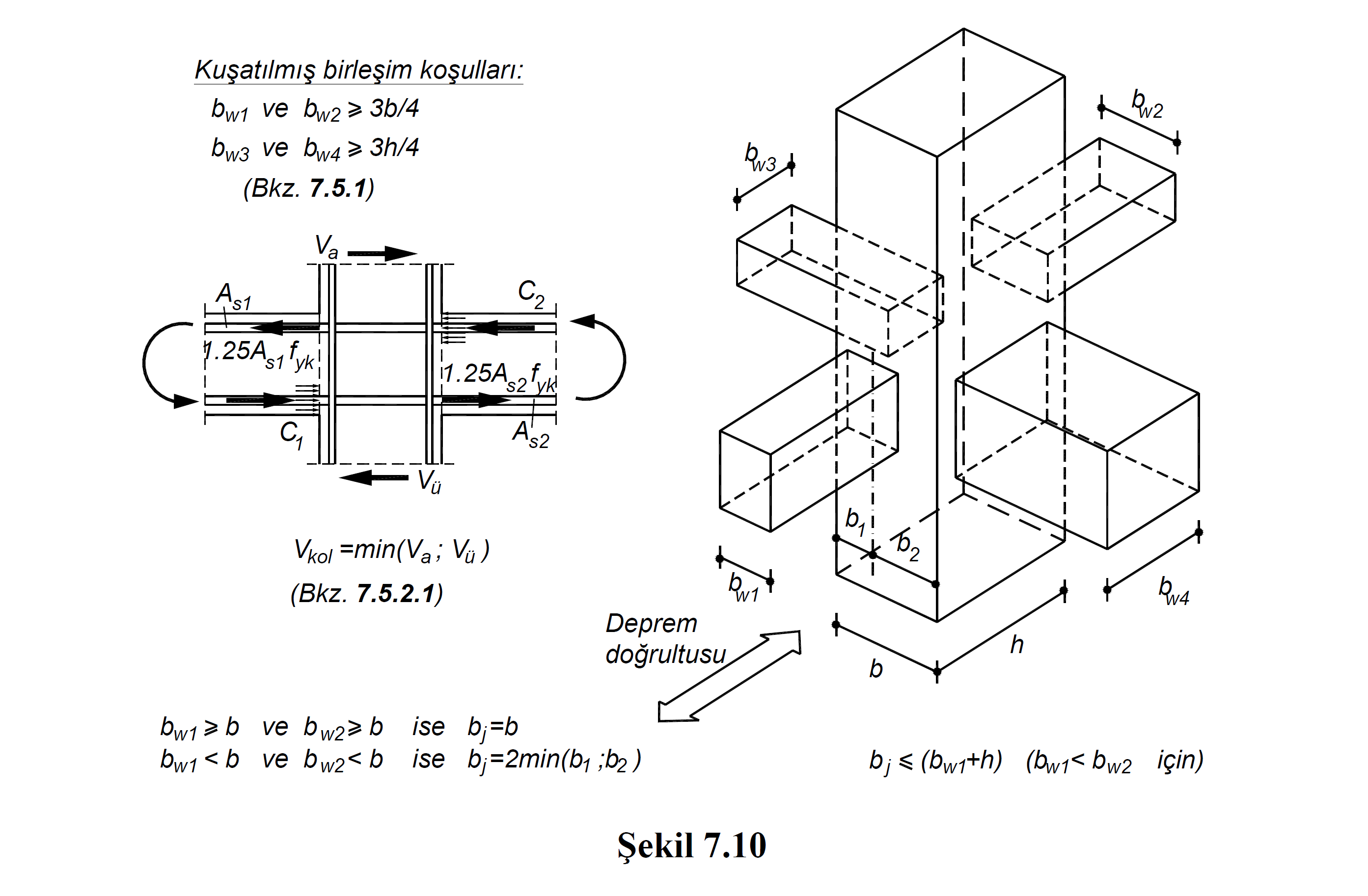
7.5.2.2 - The shear force calculated with Equation (7.11) in any junction area will never be determined by Equation. (7.12) and Equation. It shall not exceed the limits given in (7.13) ( Figure 7.10 ). If these limits are exceeded, the earthquake calculation will be repeated by increasing the column and / or beam cross-section dimensions.
(a) In confined joints:

(b) In unconfined joints:

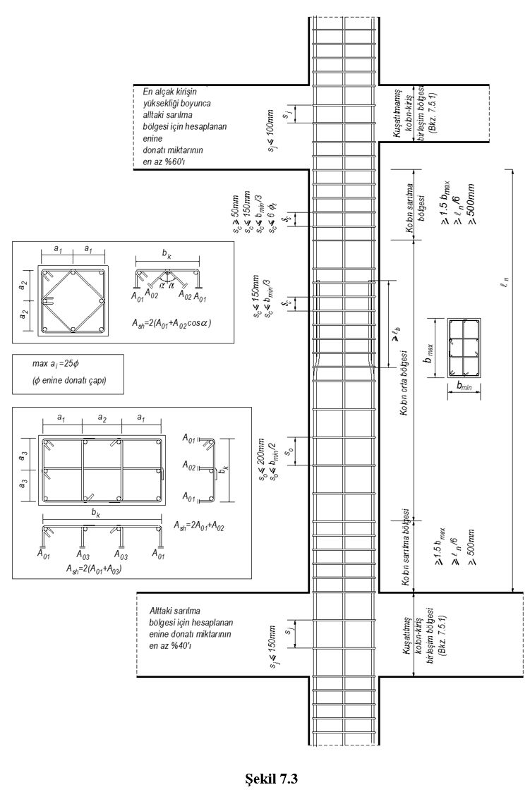
7.5.2.3 - The minimum transverse reinforcement conditions in the column-beam junction are given in (a) and (b) below ( Figure 7.3 ):
(a) In confined joints, at least 40% of the amount of transverse reinforcement calculated for the confinement zone of the column below shall be used throughout the joint zone. However, the diameter of the transverse reinforcement shall not be less than 8 mm and the spacing shall not exceed 150 mm.
(b) In unconfined joints, at least 60% of the amount of transverse reinforcement calculated for the confinement zone of the column below shall be used throughout the joint zone. However, in this case, the diameter of the transverse reinforcement shall not be taken less than 8 mm and the spacing shall not exceed 100 mm.
Related Topics