
-
The shear strength of the wall sections, V r , is automatically calculated with Equation (7.17) .
-
The design shear force, V e value is automatically checked whether the conditions given in Equation (7.18) are met.
ICONS
A ch = Gross cross-sectional area of each shearwall segment, slab or each slab in a hollow slab
f ctd = Design tensile strength ofconcrete
f ck = Characteristic cylinder compressive strength of concrete
f ywd = Design yield strength of transverse reinforcement
V e = Shear force taken as basis for transverse reinforcement calculations in columns, beams, junctions and walls
V r = Shear force ofcolumn, beam or shearwall section
ρ sh = Volumetric ratio of horizontal web reinforcements in the wall
Polygon walls are modeled with shell finite elements and the wall section is defined in the center of gravity so that these finite elements provide the condition for three-dimensional rigid body motion. The internal forces of the polygon shearwall are obtained by summing the values obtained from the shearwall finite element results of the respective loading combination at this center of gravity. In TBDY Section 7.6.6.3 , the design shear force of polygonal walls, how to find the value of V e and “Design Shear Forces for Polygonal Cross-Section Walls Under the title:Design Shear Forces for Polygonal Cross-Section Walls , the design shear forces found in polygon screens and how these forces are transferred to the polygon shearwall arms are explained in detail.
The shear capacity of polygonal walls is calculated by finding the shear capacities of the shearwall arms related to the shape described in Section 7.6.7 of TBDY , after finding the design shear force falling on each arm . The most unfavorable situation is calculated by comparing the Design Shear Force, V e , shear strength, V r , calculated in all loading combinations . While calculating the shear strength of polygonal walls, the shear strength of each arm is taken into account separately. shearwalls perpendicular to the arm compatible with the direction of the shear force should not be taken into account in the shear strength calculation. ideCAD does not take into account the contribution of these shearwall arms (shearwall arms perpendicular to the shear force direction) to the shear strength.
Shear strength for each polygonal shearwall rod is calculated according to V r TBDY Equation 7.17 .

In this equation, A ch is the gross cross-sectional area of the polygon shear arm without gap or polygon shear arm with tie beam. f ctd is the design tensile strength of concrete and f ywd is the design yield strength of the shear transverse reinforcement. ρ sh is the volumetric ratio of the horizontal web reinforcement of the polygon wall arm.
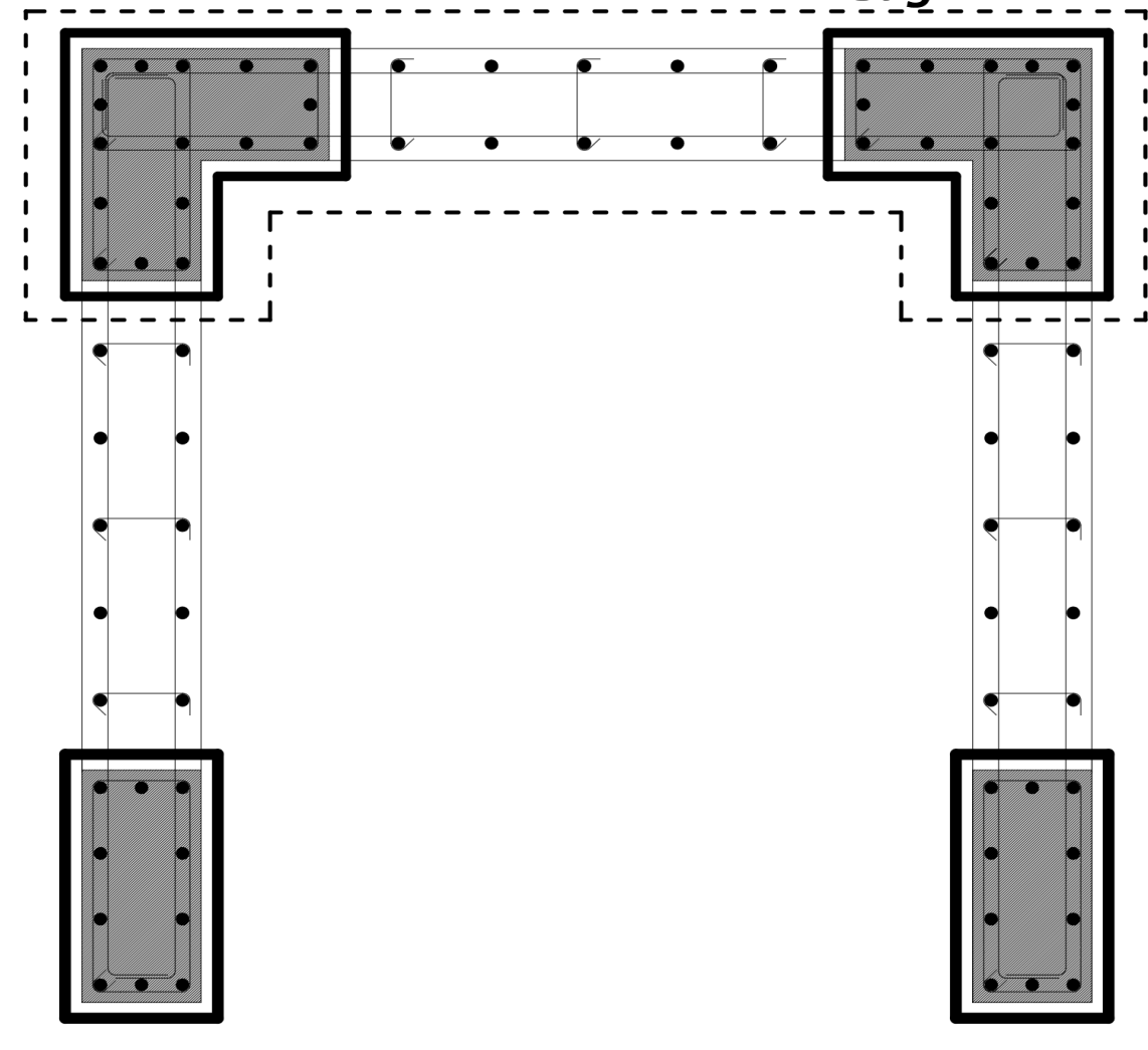
When calculating the shear strength Vr value for polygon shearwall arms, the transverse reinforcements of the relevant branch, the transverse reinforcements of the cap area and the transverse reinforcements in the cap areas where the shearwall arms meet are taken into account. The transverse reinforcements considered for the calculated Vr value for the shearwall arm marked in the figure below are shown.
TBDY Equation 7.17 exists separately for each polygonal fret arm. In this case, A ch is equal to the product of the thickness of the polygon shearwall arm and the length in the plan of the polygon shearwall arm. The horizontal web reinforcement volumetric ratio of the polygon shear arm is used in the calculation of ρ sh .
Considering the shear force capacity of the wall section created by the contribution of concrete and reinforcement and the prevention of non-ductile power depletion caused by the shear force, the following upper limits are foreseen for the design shear force. These upper limits are specified in TBDY Equation 7.18 .
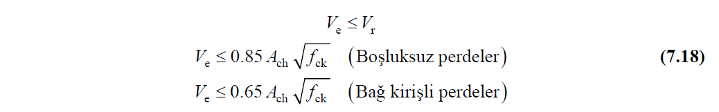
Design shear force calculated according to TBDY Section 7.6.6.3 for each loading combination , V e , TBDY calculated shear strength for polygonal wall arm in Equation 7.17 , V r and TBDY 0.85A for bulkheads defined in Equation 7.18 . ch (f ck ) 1/2 , 0.65A ch (f ck ) 1/2 for shearwalls with gaps . At the upper limit values, A ch is the product of the thickness of the polygon shearwall arm and the plan length of the polygon shearwall arm. f ck is the characteristic compressive strength of concrete.
The design shear force, V e , found for each loading combination, may create different adverse conditions in each polygon shearwall arm. For a single polygon screen, the shear strength of polygon shearwall arms calculated in accordance with the direction of shear force can create the most unfavorable situation in different loading combinations. For this reason, ideCAD Statik calculates the most unfavorable condition for each shearwall arm by making the calculation described above in all loading combinations for all group shearwall arms.
Next Topic
Related Topics