
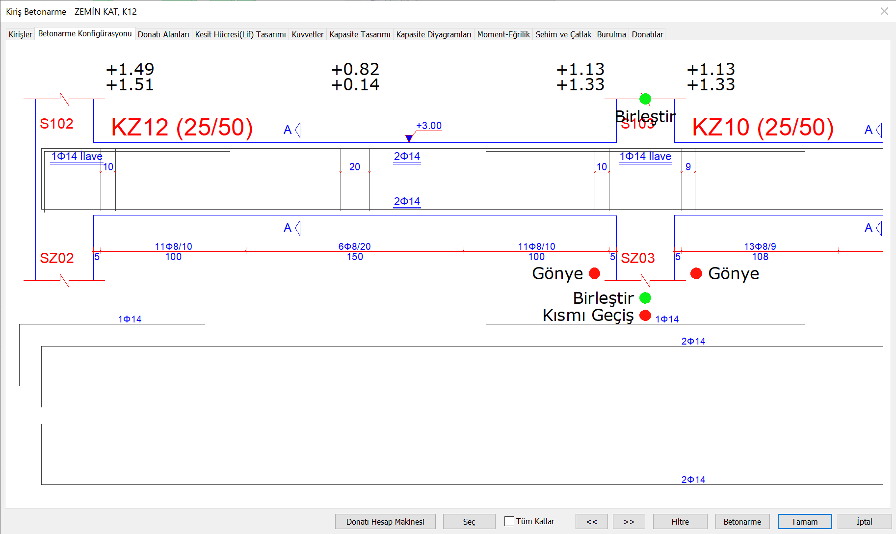
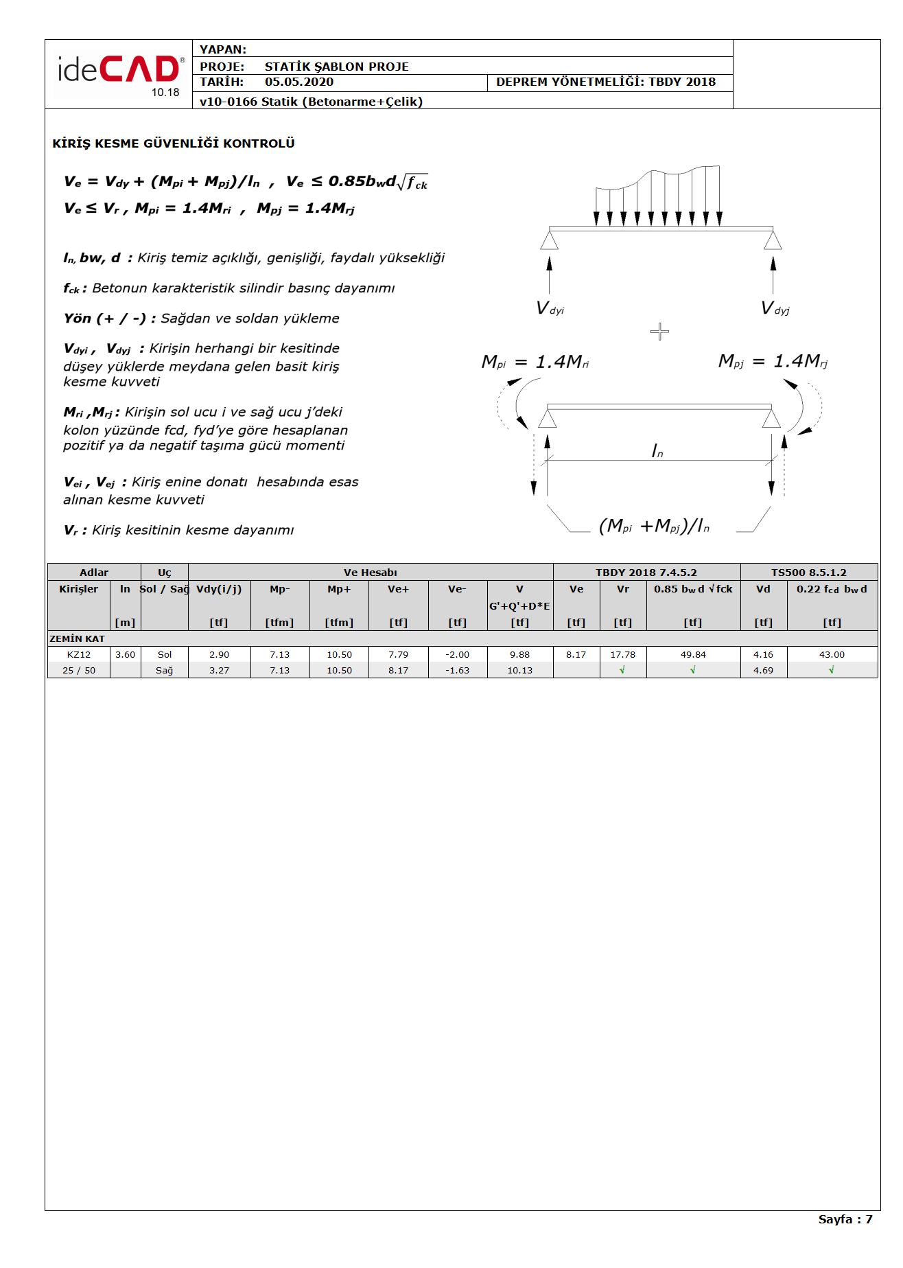
In this example, the beam shear safety control of a beam element of 25x50 dimensions, which is described in TBDY Section 7.4.5 , will be made. The reinforcement arrangement in the beam is shown in the picture below.
Material: C25 S420
f ck : Characteristic cylinder compressive strength of concrete, f ck = 25 MPa
f cd : Design compressive strength of concrete, f cd = f ck / 1.5 = 16.67 MPa
f yk : Characteristic yield strength of longitudinal reinforcement, f yk = 420 MPa
f yd : Design yield strength of longitudinal reinforcement, f yd = f yk / 1,15 = 365.22 MPa
f ywk : Characteristic yield strength of transverse reinforcement, f ywk = 420 MPa
f ywd : Design yield strength of transverse reinforcement, f ywd = f ywk / 1,15 = 365.22 MPa
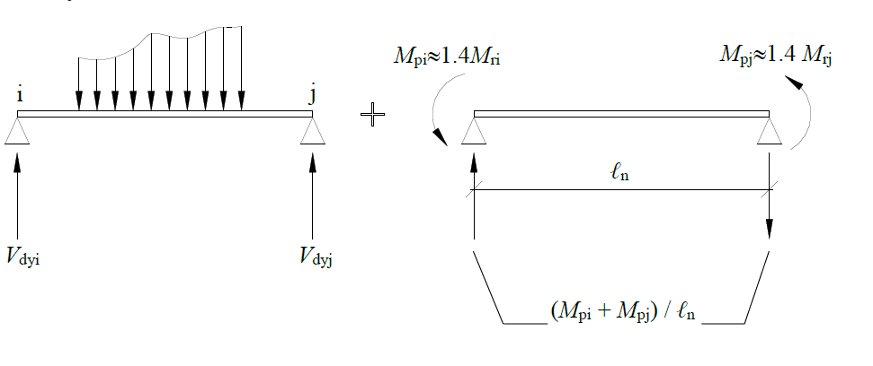
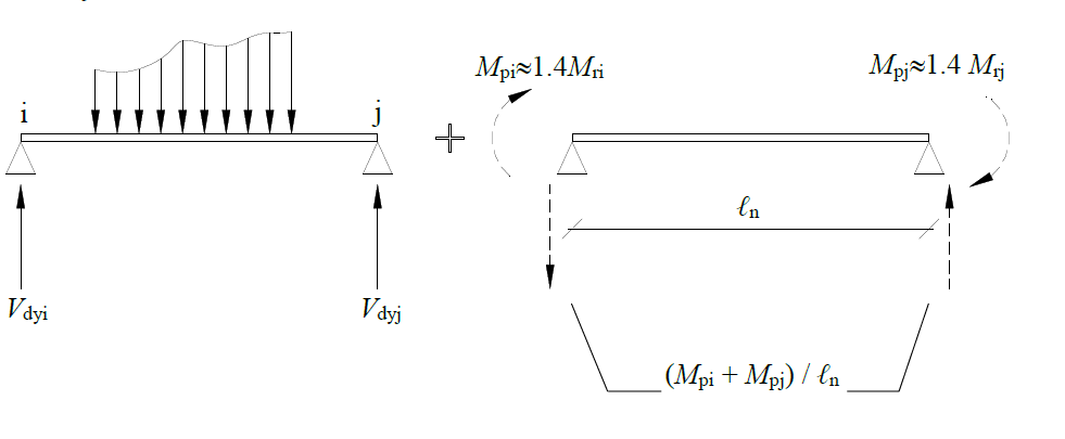
According to Article 7.4.5.1 of TBDY , the shear force V e to be taken as basis in calculating the transverse reinforcement in beams should be found by Equation 7.9 in a way to give unfavorable results separately for the directions of earthquake .

In this equation, V dy is the simple beam shear force value caused by vertical loads in any section of the beam. M pi and M pj is the positive or negative moment capacity calculated by taking into account the strength increase of f ck , f yk and steel on the column face at the beam ends . l n is the free span of the beam between the column faces.
At the left (i) end of the sample beam, V dy (i) = 2.90 tf and at the right (j) end V dy (j) = 3.27 tf.
In the moment curvature analysis using the material models f cd = f ck / 1,5 = 16.67 MPa and f yd = f yk / 1,15 = 365.22 MPa, the values of M ri and M rj can be found. These values are the bearing strength moments of the beam found by the DGT approach. However, since there are different reinforcements at the i and j ends of the beams in different directions, there should be separate bearing strength moments for both directions at both ends.
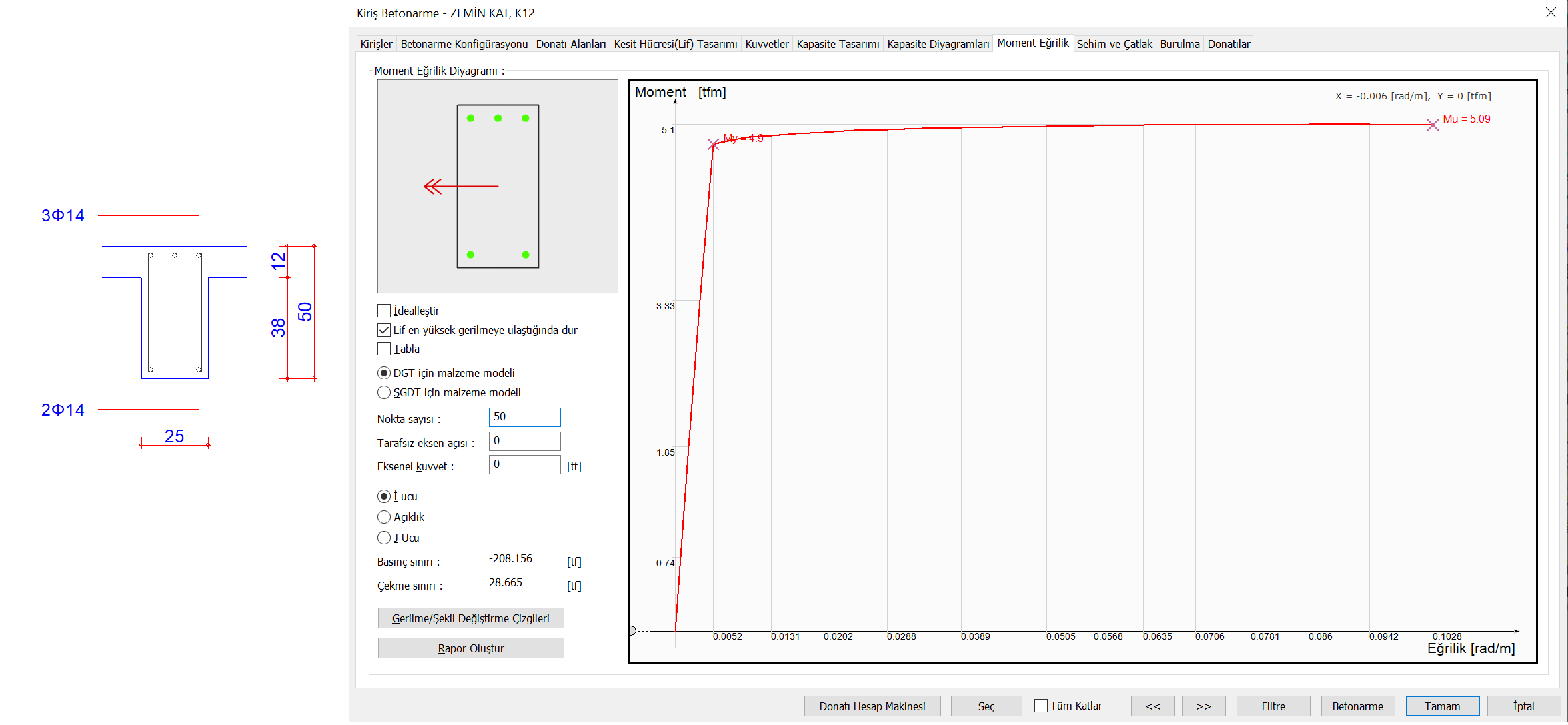
A moment curvature analysis can be performed for the moment in the positive (+) direction of M ri at the left (i) end of the sample beam , as shown in the picture below. Since the DGT approach is used here, concrete material f cd and longitudinal reinforcement material f yd are used. In this case, the carrying power moment (Mu value in the moment curvature analysis ) is calculated as M ri (+) = 5.09 tfm. Considering the right hand rule, it is seen that there is pressure on the upper side of the tension on the lower side of the beam according to the direction of the moment vector. In this case, the reinforcements that receive tensile stress are 2Φ14 lower bars.
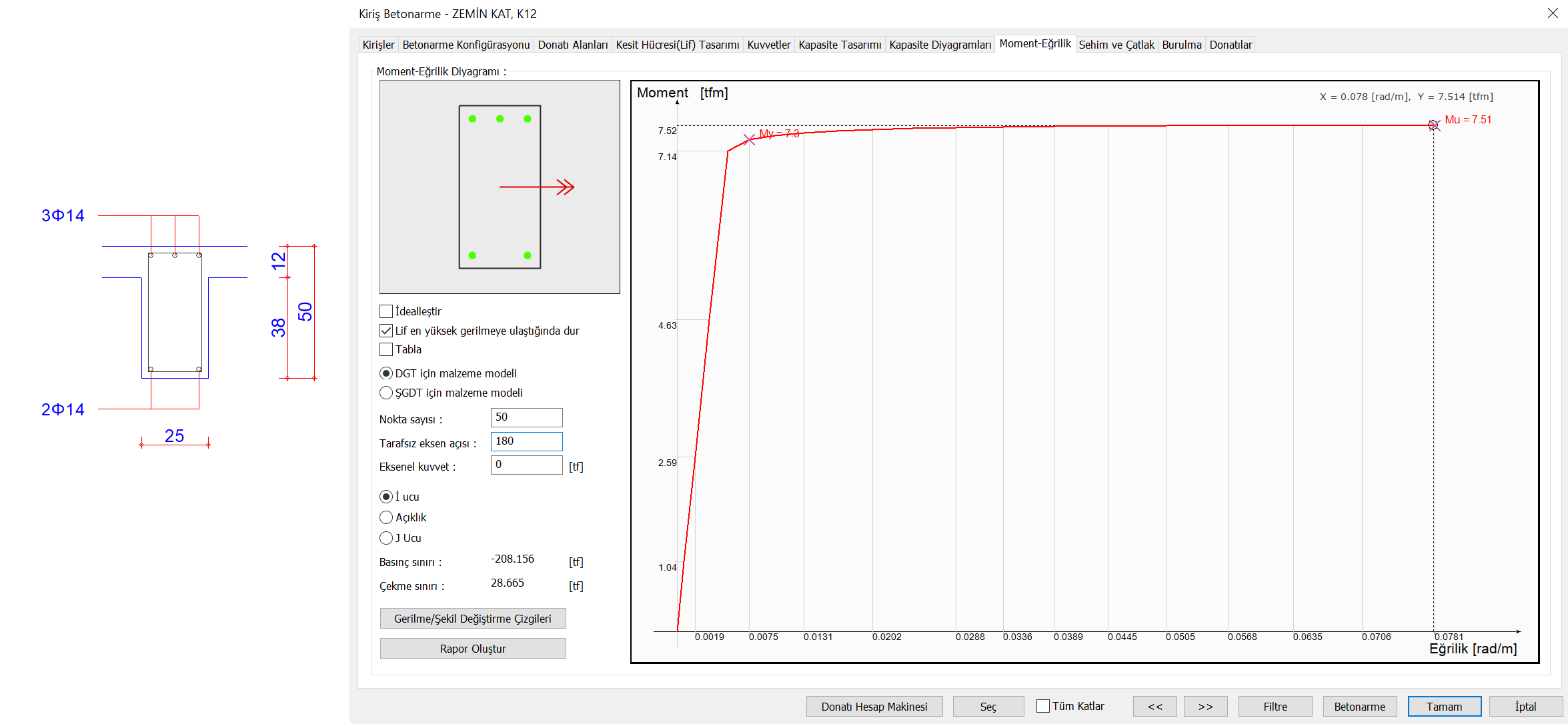
Example beams of the left (i) the end of the M r negative (-) as well as a moment curvature analysis made in the image below for torque in direction. Since the DGT approach is used here, concrete material f cd and longitudinal reinforcement material f yd are used. In this case, the carrying power moment (Mu value in the moment curvature analysis ) was calculated as M ri (-) = 7.51 tfm. Considering the right hand rule, it is seen that there is pressure on the upper side of the tension on the lower side of the beam according to the direction of the moment vector. In this case, the reinforcements that receive tensile stress are the top reinforcements of 3Φ14.
Since the same reinforcements are placed at the right (j) end of the beam, M rj (+) = 5.09 tfm and M rj (-) = 7.51 tfm.
M pi and M pj is the positive or negative moment capacity calculated by taking into account the strength increase of f ck , f yk and steel on the column face at the beam ends . Since the characteristic strength of the concrete and the characteristic strength of the reinforcement are reduced while finding M ri , and also since the breaking stress of the reinforcement f su ≈ f yk / 1.25, the capacity moments can be taken into account as 1.4 times the bearing strength moments.
In this case, for the positive (+) and negative (-) directions at the left (i) end of the beam,
Mpi(+) ≈ 1.4Mri(+) = 1.4*5.09 = 7.13 tfm
Mpi(-) ≈ 1.4Mri(-) = 1.4*7.51 = 10.51 tfm
For the positive (+) and negative (-) directions at the right (j) end of the beam,
Mpj(+) ≈ 1.4Mrj(+) = 1.4*5.09 = 7.13 tfm
Mpj(-) ≈ 1.4Mrj(-) = 1.4*7.51 = 10.51 tfm
found as. The clear span calculated from the column surfaces was calculated as l n = 3.6 m.
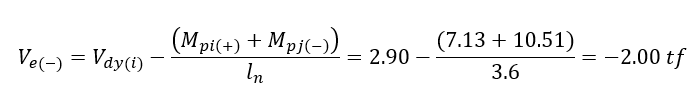
In this case, the following procedures are applied for an earthquake direction (eg + Y). Opposite moments occur at the left (i) right (j) ends of the beam. Therefore, the strengths in M pi (-) and M pj (+) directions are taken into account in Equation 7.9 . The free body diagram below shows the direction (hence the moment capacities) of the plastic moments that may occur due to this earthquake.
M pi (-) = 10.51 tfm M pj (+) = 7.13 tfm
In this case, according to the above free body diagram, the shear force generated at the left (i) end of the beam is
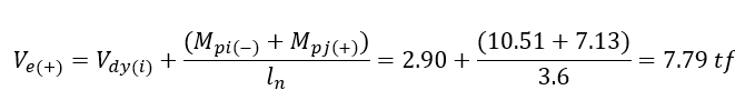
and the shear force generated at the right (j) end,
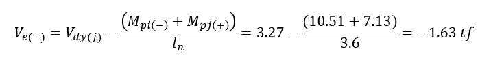
was found as. The following procedures are applied for the earthquake direction opposite to the above earthquake direction (for example -Y). Opposite moments occur at the left (i) right (j) ends of the beam. For this reason, the strengths in M pi (+) and M pj (-) directions are taken into account in Equation 7.9 . In the free body diagram below, the direction of the plastic moments (hence their moment capacities) that may occur due to the earthquake opposite to the above earthquake is shown.
In this case, the shear force generated at the left (i) end of the beam according to the free body diagram above,
and the shear force generated at the right (j) end,
was found as.
If we sum up the above values, for the left (i) end of the beam;
V e (+) = 7.79 tf and V e (-) = -2.00 tf values were found. For the left (i) end, the shear force value greater than these two values is considered as V e = 7.79 tf. If the shear force calculated from the earthquake effects increased with the Resistance Excess Coefficient D and the vertical loads according to the TBDY Article 7.4.5.1 , if the shear force calculated by TBDY Equation 7.9 is less than V e , the design shear force of the beam element is considered as this shear force. V e = 7.79 tf value for the left (i) end of the beam Equation 7.9is the value calculated with. The shear force calculated from the earthquake effects increased with the Resistance Excess Coefficient D together with the vertical loads at this end, was found as 9.88 tf. Since this value is not less than the value calculated by Equation 7.9 , the shear force to be used in reinforcement design for the left (i) end of the beam has been calculated as V e = 7.79 tf.
The above calculation should also be repeated for the right (j) end of the beam. For the right (j) end of the beam;
V e (-) = -1.63 tf and V e (+) = 8.17 tf values were found. For the right (j) end, the shear force value higher than these two values is considered as V e = 8.17 tf. If the shear force calculated from the earthquake effects increased with the Resistance Excess Coefficient D and the vertical loads according to the TBDY Article 7.4.5.1 , if the shear force calculated by TBDY Equation 7.9 is less than V e , the design shear force of the beam element is considered as this shear force. V e = 8.17 tf value for the right end (j) of the beam Equation 7.9is the value calculated with. The shear force calculated from the earthquake effects increased by the Resistance Excess Coefficient D together with the vertical loads at the right (j) end was found as 10.13 tf. Since this value is not less than the value calculated by Equation 7.9 , the shear force to be used in reinforcement design for the right (j) end of the beam is calculated as V e = 8.17 tf.
Since the beam shear reinforcements are placed symmetrically, the shear force values found for the left (i) end and right (j) end and to be taken as basis in the transverse reinforcement calculation were found to be 7.79 tf and 8.17 tf, respectively. In this case, according to the TBDY Article 7.4.5.1 , the ultimate shear force to be used in the beam transverse reinforcement calculation, taking into account the most negative of these two shear forces,
V e = 8.17 tf
found as.
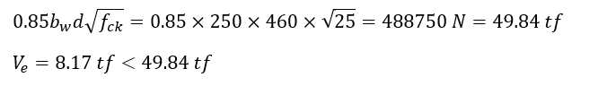
7.4.5.2 TBDY substance according to her, 7.4.5.1 'calculated according to the shear force, V e , Eq. (7.10) shall satisfy the conditions given.

Shear strength, V r value is calculated as the sum of concrete additive (V c ) and shear reinforcement additive (V w ) as shown below in accordance with TS500 Section 8.1.4 . However, it is stated in the Article 7.4.5.3 of TBDY that the contribution of concrete to shear strength should be taken as zero (V c = 0). Taking these conditions into consideration, the shear strength is calculated as follows.
As can be seen from the reinforcement arrangement, the shear reinforcement in the beam confinement region is defined as Φ8 / 10. Since this reinforcement is a reciprocal arm, the cross section area of the cross section is calculated as A sw = 2 * ((π * 8 2 ) / 4) = 100.531 mm 2 . Stirrup spacing is s = 100 mm. Since the beam length is 50 cm and the cover is 4 cm, the beam useful height is calculated as d = 500-40 = 460 mm. In this case, V r value
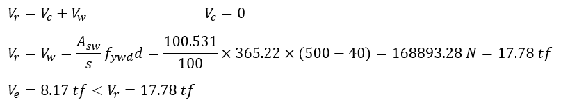
found as. In this case, this condition has been fulfilled.
For the second equation given in Equation (7.10) ;
found as. In this case, this condition is met. These calculations are made in all loading combinations including earthquake load.
For loading combinations that do not contain earthquake loads, the upper limit of shear force control given in TS500 Equation 8.7 and calculated to prevent crushing of the body concrete is done with the following steps.
Shear forces generated in the beam due to the 1.4G + 1.6Q loading combination, V d ,
V d = 4.16 tf for left (i) end
V d = 4.69 tf for right (j) end
calculated as. In this case,
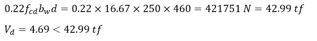
The condition is satisfied.
All the controls and calculation values described above are specified in a "Beam Shear Safety Control" report shown below.
Next Topic