
You can examine the normal force, shear force and moment values of the rod elements according to the local axes of the element.
Location of Frame Results View Feature
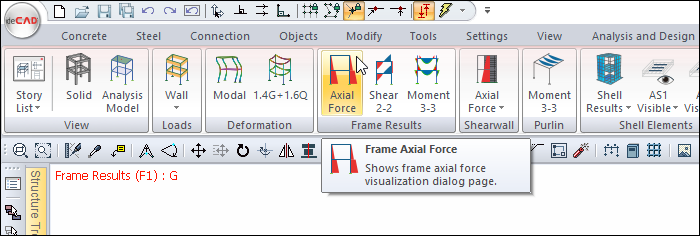
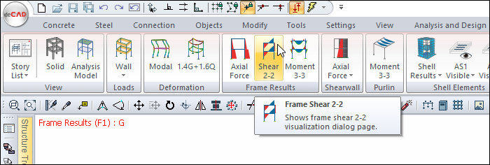
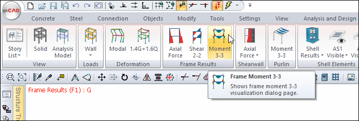
You can access the Frame Results tab by clicking one of the axial force, shear force and moment commands under the Frame Results heading of the Ribbon menu Structural Inspection tab .
You can also access the Frame Results tab by clicking the Analysis Model command under the Ribbon menu, Concrete tab, Structural Inspection heading .
Frame Results Tab
|
Specifications |
|---|
|
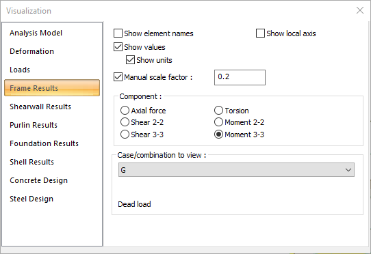
Show element names If checked, the names of the elements corresponding to the elements folder in the structure tree are shown above each element. |
|
Show local axis If checked, show local axis of the elements are shown on the elements. |
|
Show values If checked, the values of the diagrams will be shown on the structure. |
|
Show units If show values is checked, it will be active. If marked, the units belonging to internal forces will be shown on the structure. |
|
Manual scale factor If the option is not selected, the scale factor deemed appropriate by the program is applied for internal force diagrams. If checked, the desired scale factor value can be entered manually in the box to the right. |
|
Component 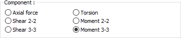
Normal force, shear force and moment values occurring in rod elements are displayed for any selected combination in the element local axes. For clarity, the sample screenshots are arranged as a single frame, single layer. Example of Vertical Loads Moment 3-3 Diagram 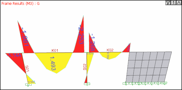
Example of Vertical Load Shear 2-2 Diagram 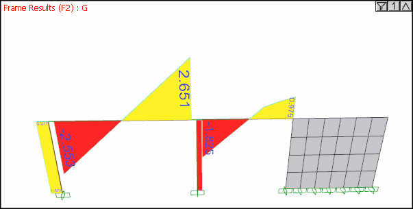
Example of Vertical Loads Axial Force Diagram 
Earthquake Load Axial Force Diagram 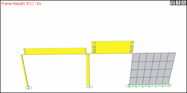
|
|
Case/combination to view 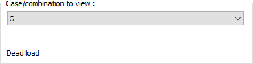
By selecting the appropriate load combination from the list, the internal forces generated in the frame elements due to this combination, selected in the component tab, can be graphically examined on the structure. |
Next Topic