
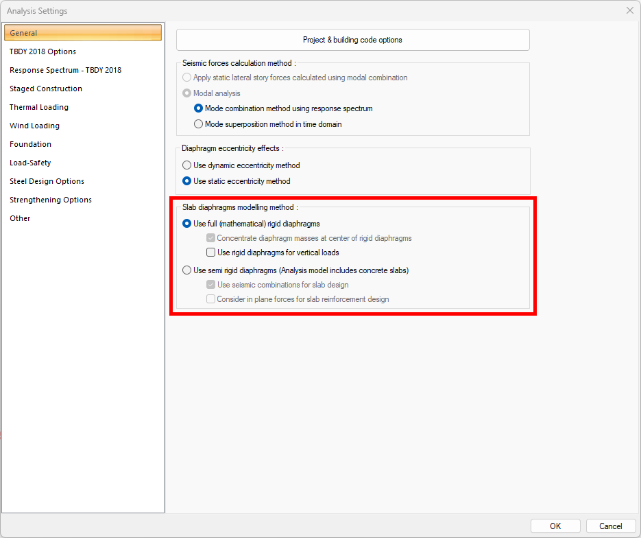
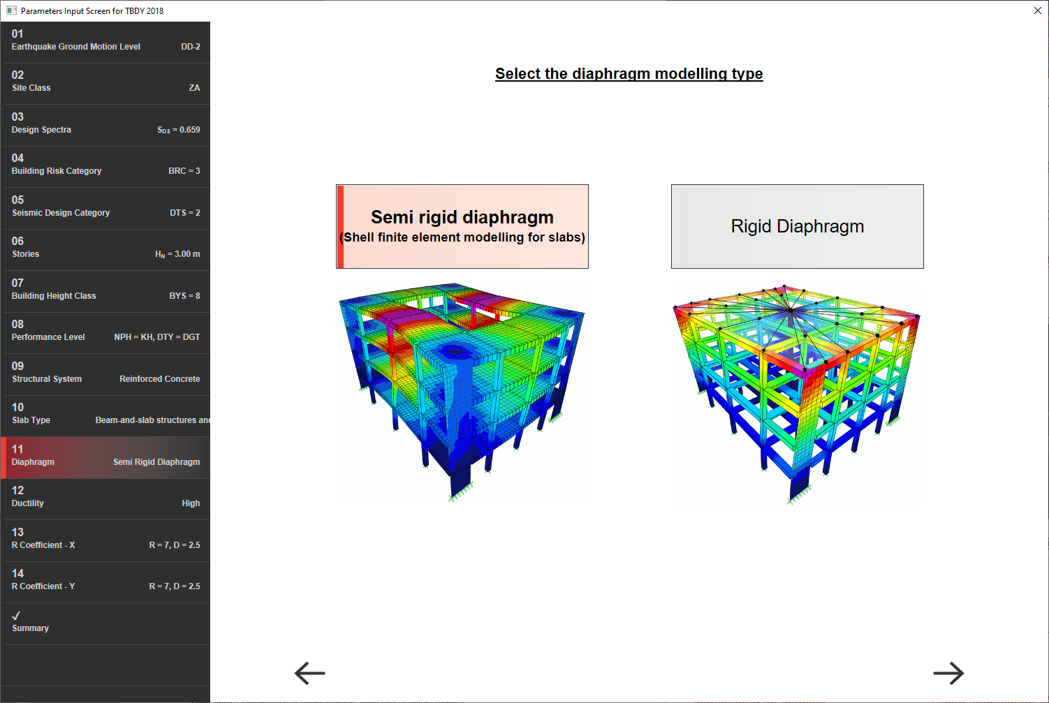
In building analysis, floors can be modeled in two different ways. The first of these is the Fully Rigid Diaphragm Adoption , where in-plane motion is neglected, assuming that the in-plane stiffness of the slabs is very high . The second is the Semi-Rigid Diaphragm Adoption , in which slab in-plane stresses and movement can occur, taking into account the stiffness of the slabs in the analysis model . It can be selected with the image shown below in the analysis settings.
Download ideCAD for ACI 318-19
1- Fully Rigid diaphragm:
The rigidity of the slab; The system is accepted as a rigid diaphragm if the vertical bearing system elements designed to meet the effects of earthquakes are considerably larger than the stiffness. The difference between the center of mass and the center of rigidity causes twisting in the plan. According to Article 3.6.2.2 of TBDY , rigid diaphragm acceptance cannot be applied in buildings with A2 and A3 type irregularities.
Analysis with the Fully Rigid diaphragm is based on the assumption that there is no or very little in-plane deformation under the effect of earthquakes. Since there is no such deformation, in-plane stresses will not appear in the analysis model. The earthquake calculation is made by gathering the masses in the floor center of gravity. The analysis model of a building that is solved with the acceptance of Full Rigid Diaphragm is as shown below.
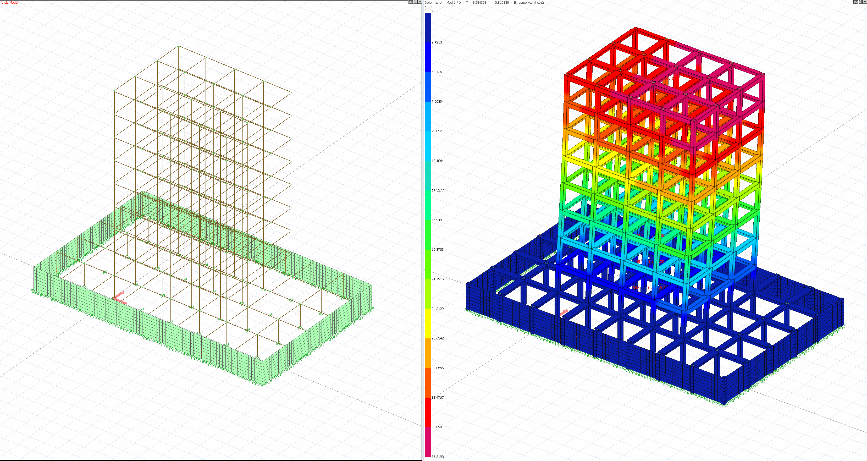
As seen in the picture above, only the curtains are modeled with two dimensional finite elements. Columns and beams are modeled with frame elements.
Applicability ( Fully Rigid Diaphragm ): It is the most appropriate method when the stiffness of the structural system elements that meet the effects of earthquake is less than the stiffness of the slab. It is a common acceptance for reinforced concrete and composite floors. Analysis needs to be simplified in order to make practical design. Often an idealized rigid diaphragm is a suitable choice to simplify the analysis.
2- Semi Rigid diaphragm:
Floor stiffness; It is an analytical model representing situations where the system is close to or equal to rigidity. Stiffness calculation is calculated depending on slab thickness, dimensions and material parameters. The semi-rigid diaphragm acceptance is the acceptance that reflects the most realistic behavior of the laying behavior in the structural analysis model. In the semi-rigid diaphragm model, floors are modeled with two dimensional finite elements (shells). Two dimensional finite elements create stresses on the shell element by their in-plane out-of-plane movement. According to this stress distribution, reinforced concrete slab design can be made.
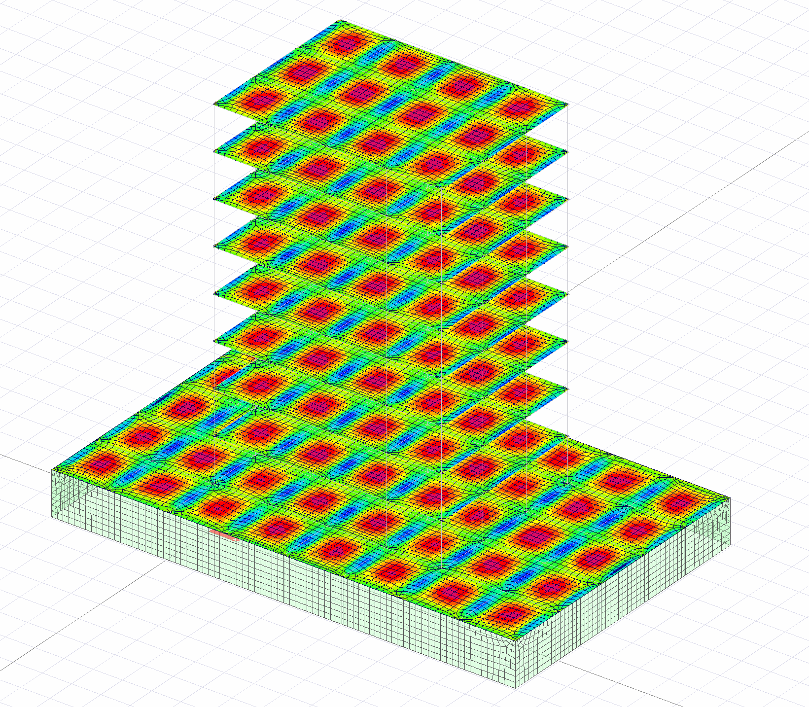
Analysis with semi-rigid diaphragm is based on the assumption that in-plane and out-of-plane deformation under the effect of earthquakes and the stresses resulting from these deformations are distributed over two-dimensional finite elements. Since the slabs are included in the analysis model, the stresses and strains can be seen in the analysis model. The analysis model of a building with the acceptance of Semi-Rigid Diaphragm is as shown below.
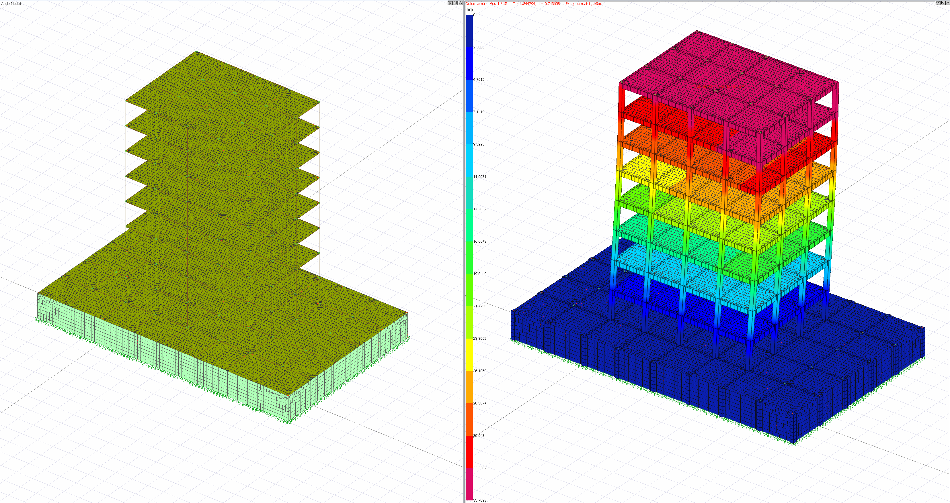
As seen in the picture above, there are in-plane deformations of the floors in the deformed system in the 3D analysis system.
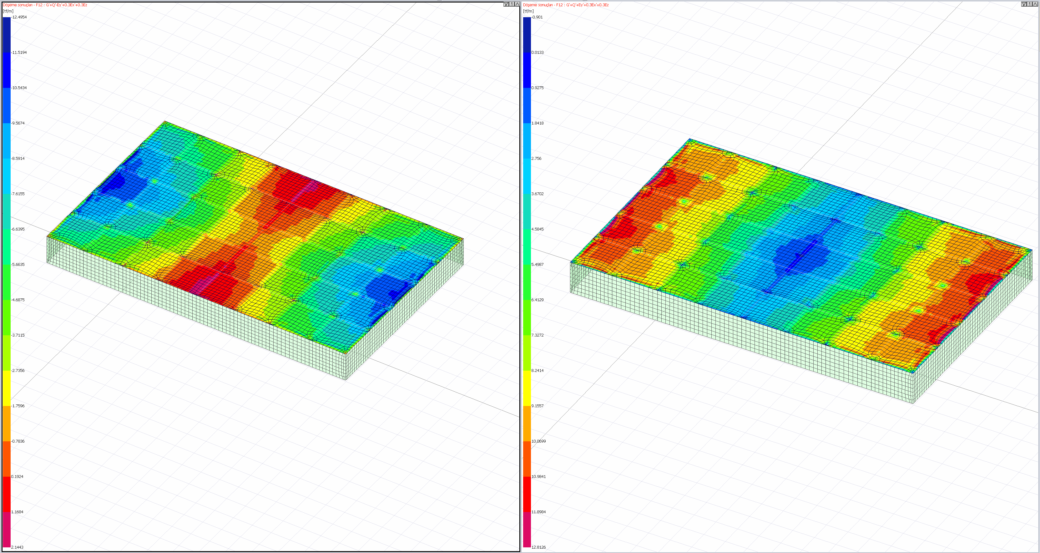
The stress distribution within the slab is variable. For this reason, the stress distribution at each point on the floors of buildings built with semi-rigid diaphragms can be examined as shown in the pictures below.
Applicability ( Semi-Rigid Diaphragm ): It is the acceptance that most accurately reflects the behavior of the flooring. The reason for this is that the rigidity of the diaphragm is taken into account in the analysis. It closely converges to real behavior in structures with irregular or large gaps in the plan. Since the analysis is made without simplification, the analysis time is longer than the rigid diaphragm. It is obligatory to accept semi-rigid diaphragm as per TBDY 2018 , especially in non-beam slab structures and buildings with A2 and A3 type irregularities .
In accordance with TBDY 2018 Articles 3.6.2.2 - 4.5.6.2 - 4.5.7.1 - 7.11.3, the in-plane and out-plane displacements of reinforced concrete slabs should be modeled with two-dimensional (shell, shell) finite elements to include degrees of freedom.