
You can examine the concrete design results on the building model.
Location of Concrete Design Outputs Feature
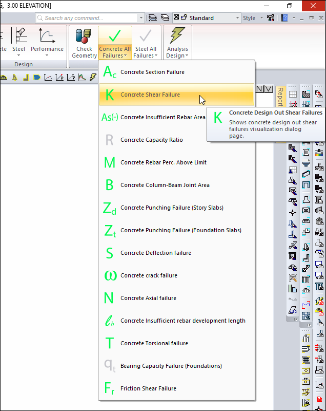
You can access the Concrete Design Output tab by clicking one of the commands under the Output title Concrete All Failures command in ribbon menu Structural Inspection tab .
You can also access the Concrete Design tab by clicking the Analysis Model command under the ribbon menu, Concrete tab, Structural Inspection heading.
Design Output Types
|
Output types and examples |
|---|
|
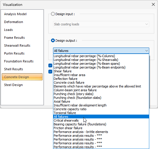
Longitudinal rebar percentage (% -Columns) 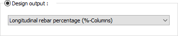
Columns with different pursuits are painted in different colors on the view window. From the scale on the left of the screen, it can be seen which color corresponds to which pursmail value in percentage. 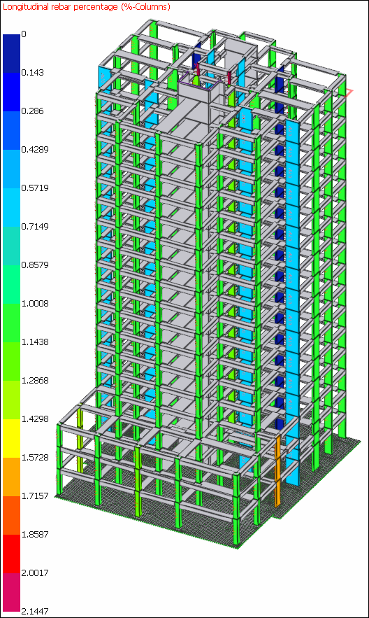
|
|
Longitudinal rebar percentage (% -Shearwalls) 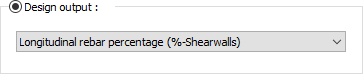
Shearwalls with different pursuits are painted in different colors in the view window. From the scale on the left of the screen, it can be seen which color corresponds to which pursmail value in percentage. 
|
|
Length of longitudinal reinforcement (% -beam openings) 
The beams with different openness strength are painted in different colors on the view window. From the scale on the left of the screen, it can be seen which color corresponds to which pursmail value in percentage. 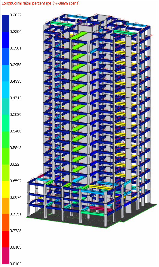
|
|
Longitudinal rebar percentage (% -Beam endpoints) 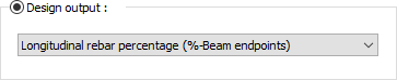
The beams with different support dimensions are painted in different colors on the view window. From the scale on the left of the screen, it can be seen which color corresponds to which pursmail value in percentage. 
|
|
Shear failure 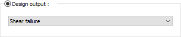
Elements that are not sufficient in terms of cutting capacity are painted red in the view window. Enough ones appear in green. |
|
Insufficient rebar area 
Elements with existing rebar in the section smaller than the required rebarss are colored red in the view window. Enough ones appear in green. 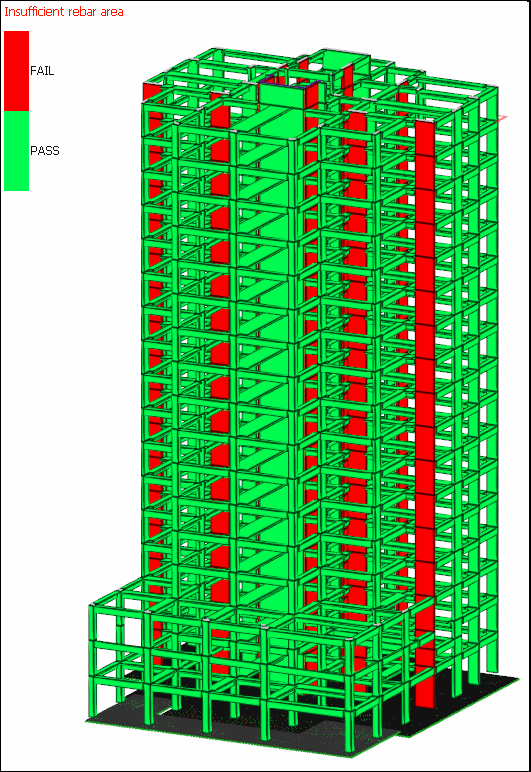
|
|
Critical shearwalls 
According to the conditions defined in TBDY 7.6.2, the critical zone height of the shearwall for which the critical shearwall height is constituted is shown in red, and the height outside the critical zone is shown in green. 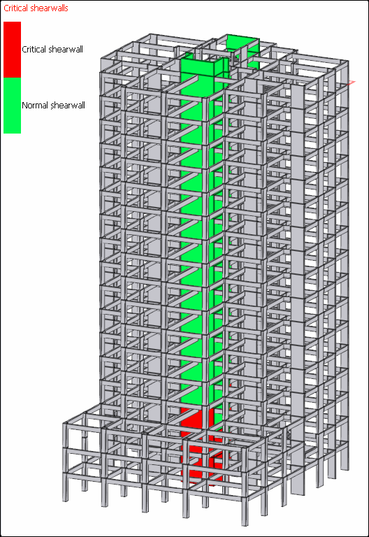
|
|
Deflection failure 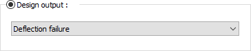
Beams that exceed the deflection limit are painted red in the view window. |
|
Concrete crack failure 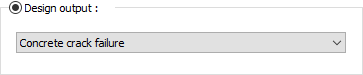
Beams that exceed the crack limit are painted red in the view window. |
|
Elements which have rebar percentage above the allowed limit 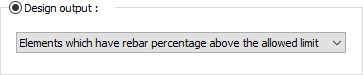
If the current rebar ratio of the element exceeds the maximum pursmail value specified in the parameter settings, the relevant elements are colored red in the view window. 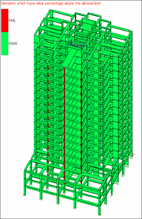
|
|
Column-beam joint area failure 
In high ductile columns, if there are column-beam joints that do not meet the TBDY 2018 7.5.2 clause, the columns forming this combination and the beams connected to these columns are painted red. 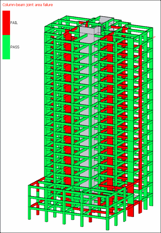
|
|
Punching check (story slabs) 
Columns and shearwalls with different staple values on story slabs are painted in different colors in the view window. It can be seen which color corresponds to which stapling value proportionally from the scale on the left of the screen. Elements with a ratio greater than 1 are colored red. |
|
Punching check (foundation slabs) 
Columns and shearwalls with different staple values are painted in different colors in the view window. Which color proportionally corresponds to which stapling value can be seen from the scale on the left of the screen. Elements with a ratio greater than 1 are colored red. |
|
Axial failure 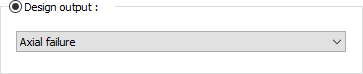
If the vertical loads on the column exceed the axial capacity, the relevant column is colored red in the display window. 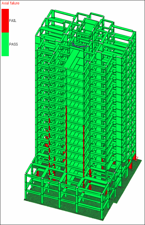
|
|
Insufficient rebar development length 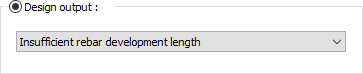
If the TBDY 2018 7.4.3.1 item option is active in the beam parameters, the elements that do not meet this criterion are colored red in the view window. 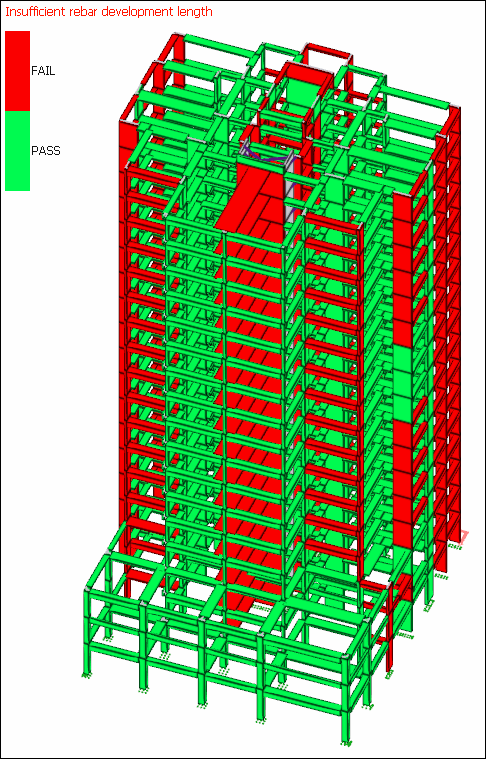
|
|
Concrete capacity ratio 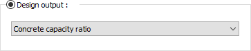
Elements with different capacity ratios are painted in different colors in the viewport. It can be seen from the scale on the left of the screen which color corresponds to the ratio value. Elements with a ratio greater than 1 are colored red. |
|
Torsional failure 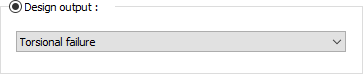
Elements that exceed the torsional capacity are painted red in the view window. |
|
All failures 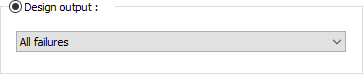
If there are elements that contain any or more of the deficiencies described above, they are colored red in the view window. 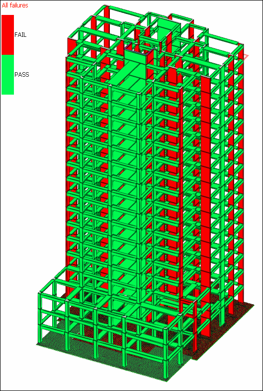
|
|
Bearing capacity failure (foundations) 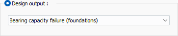
Elements exceeding the bearing capacity are painted red in the view window. |
|
Friction shear failure 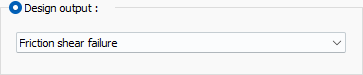
Elements with friction shear failure are colored red in the view window. |
|
Performance analysis - brittle elements 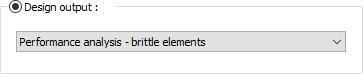
As a result of linear performance analysis, if there are brittle elements, they are colored red in the view window. 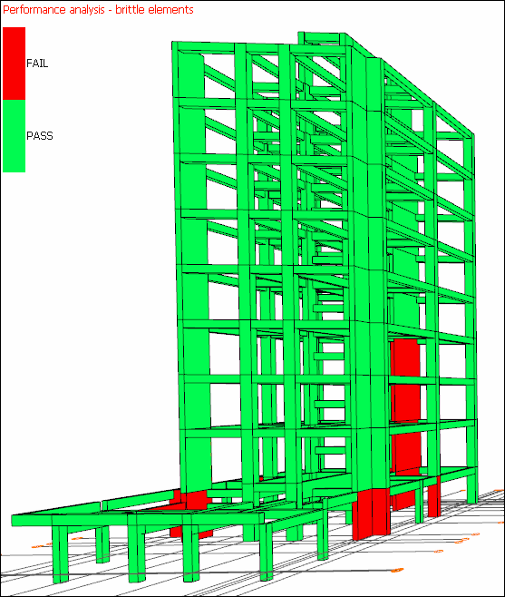
|
|
Performance analysis Damage zone occurring in the elements for a selected loading condition are displayed on the structure in the view window. Which color indicates which damage zone can be seen from the color scale on the left of the screen. 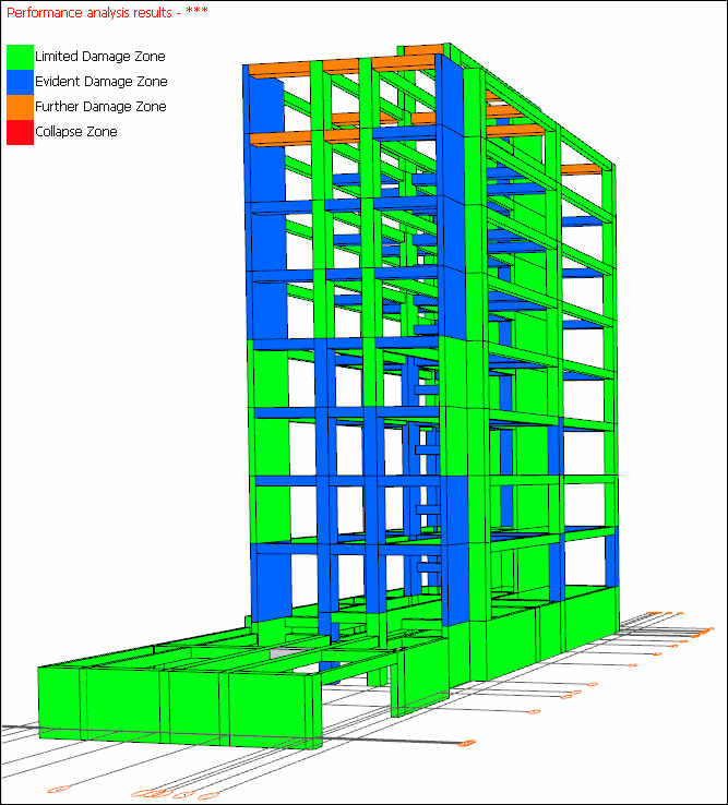
|
Concrete Design Tab
|
Specifications |
|---|
|
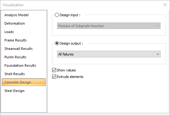
Design input 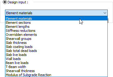
By selecting any of the options in the list, it is possible to display the input determined by the user on the building model in the view window. You can find detailed information on the title of concrete design inputs. |
|
Design output 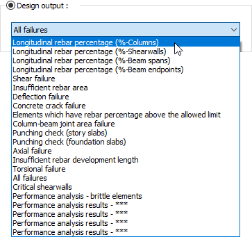
By selecting any of the options in the list, it is possible to display the input determined by the user on the building model in the view window. |
|
Show values If checked, the values of the diagrams will be shown on the structure. |
|
Extrude elements If checked, the frame system is shown as solid (solid). If not checked, it is shown as a line (bar). |
Next Topic