
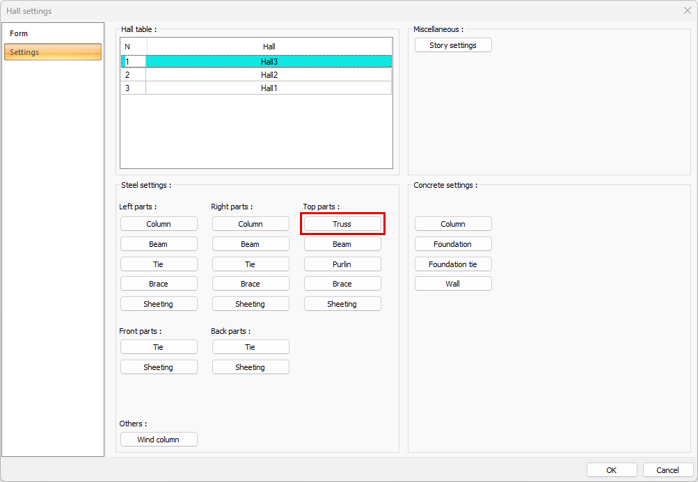
The hall steel truss settings are changed by clicking the Steel Truss button from the hall settings dialog settings tab. Truss settings are made separately for the upper part of the hall.
Location of Hall Steel Truss Settings
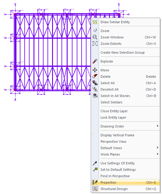
Select the hall where you want to change the steel beam settings and click the right mouse button. Click the Properties line from the right click menu that opens.
General Tab
|
Specifications |
|---|
|
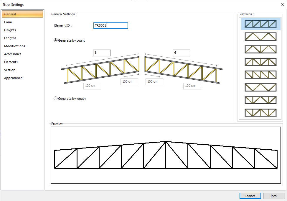
Generate by count 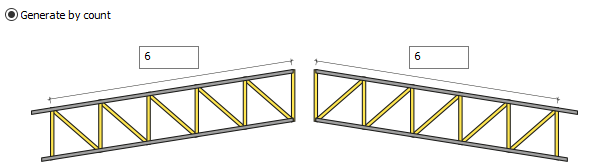
The count of patterns for both slopes of the truss can be different. After selecting the option, give the values to determine the count of patterns for the left and right inclination. |
|
Generate by length 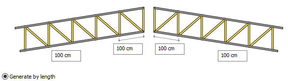
The length value is the distance between two patterns. Separate values can be given for both slopes. When create by giving length is checked, the number of patterns of the truss is found based on the truss opening. In addition, the lengths of the left and right starting eyes of the vertex can also be arranged separately. The total length is edited in the Length tab. |
|
Patterns 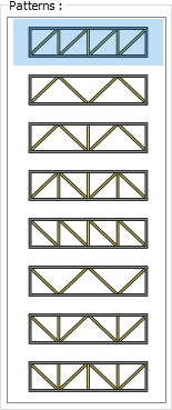
The patterns that can be used are listed. The desired pattern is selected by marking it. |
|
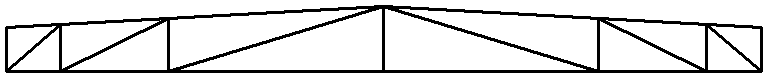
Preview 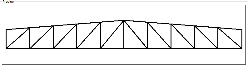
Includes a preview of the trusses. The selected type and entered values can be followed simultaneously in the preview. |
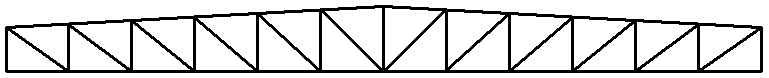
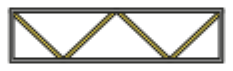
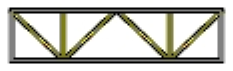
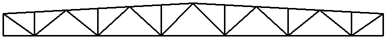
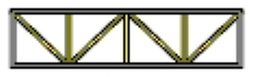
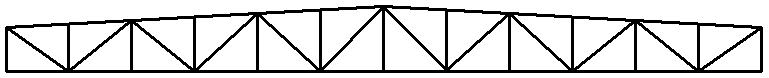
The preview images for the selected patterns are given in the table below.
|
Patterns |
|---|
|
|
|
|
|
|
|
|
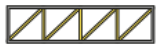
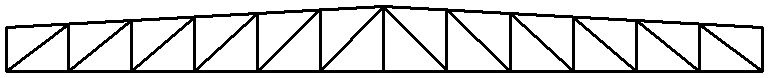
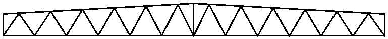
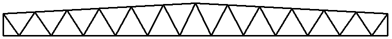
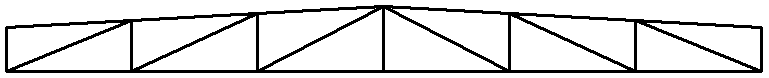
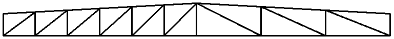
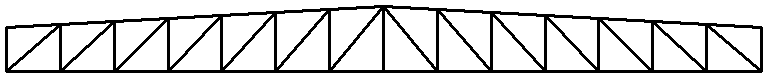
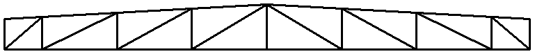
In the table below, examples of pre-images are given for the values entered in the count of patterns and pattern length.
|
Count 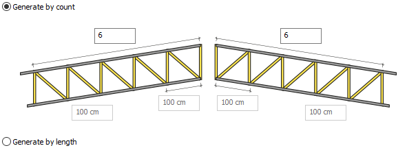
|
|
Count 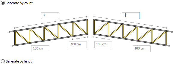
|
|---|
|
Count 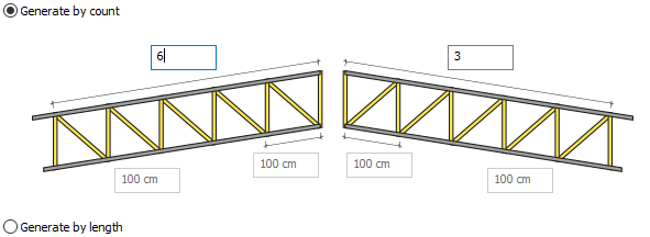
|
|
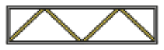
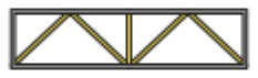
Length 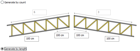
|
|
Length 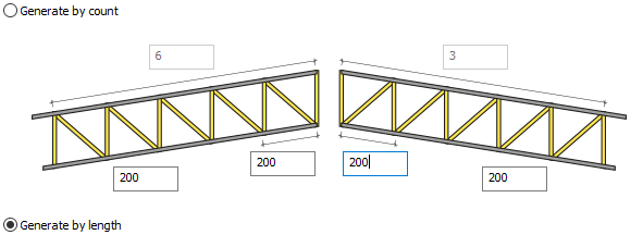
|
|
Length 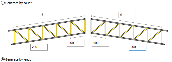
|
Form Tab
|
Specifications |
|---|
|
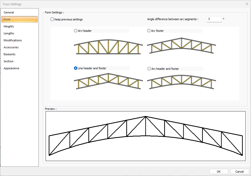
Keep previous settings Keeps the previous settings. |
|
Angle difference between arc segments The precision angle difference between arcs used when creating truss. As sensitivity increases, processing speed decreases. |
|
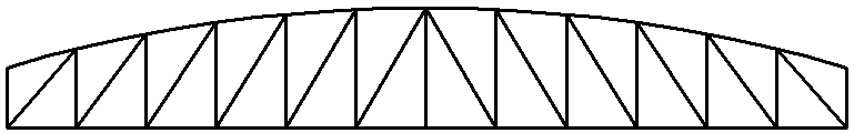
Arc header 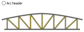
Only the top head of the truss is curvilinear. |
|
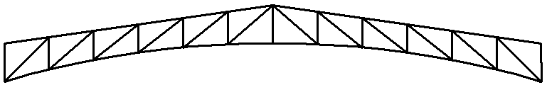
Arc footer 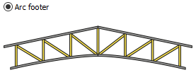
Only the bottom head of the truss is curved. |
|
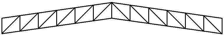
Line header and footer 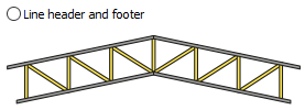
Both the top and bottom head of the truss is in linear form. |
|
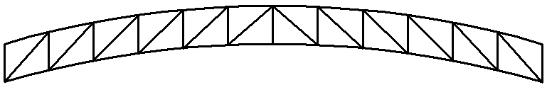
Arc header and footer 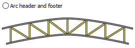
Both the top and bottom head of the truss is curvilinear. |
|
Preview 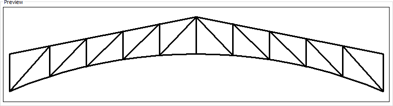
Includes a preview of the truss. The selected format can be followed simultaneously in the preview. |
The preview for the selected form type are given in the table below.
|
Form |
|---|
|
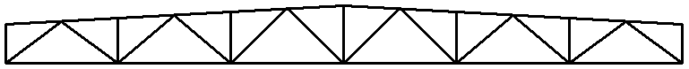
Arc header 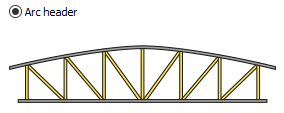
|
|
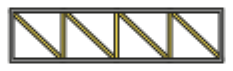
Arc footer 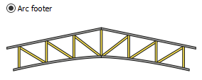
|
|
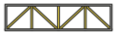
Line header and footer 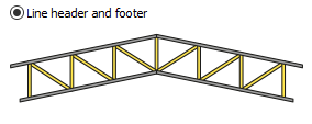
|
|
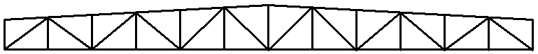
Arc header and footer 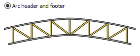
|
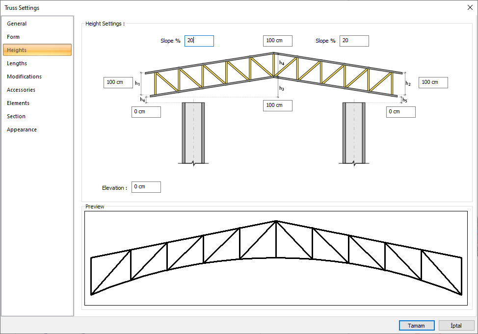
Height Tab
|
Specifications |
|---|
|
h1 It is the value that determines the height of the truss on the left slope. |
|
h2 It is the value that determines the height of the truss on the right slope. |
|
h3 It is the value determining the height of the bottom point of the truss. |
|
h4 It is the value determining the height of the top of the truss. |
|
h5 The floor is the value that determines the height of the truss right end from the base. |
|
h6 The floor is the value that determines the height of the left end of the truss from the base. |
|
Preview 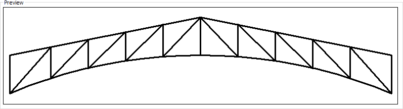
|
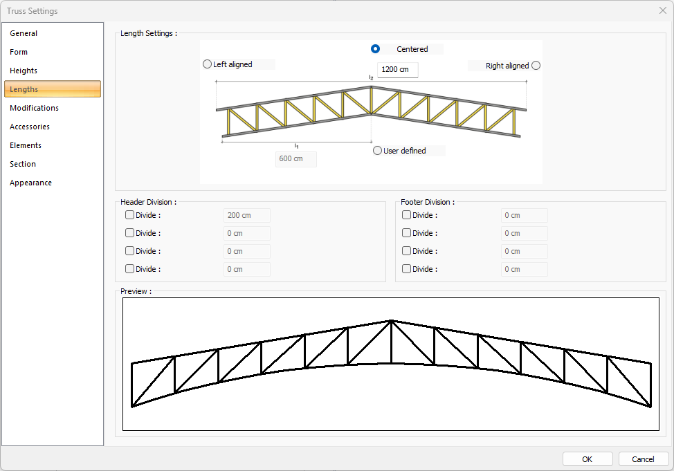
Lengths Tab
|
Specifications |
|---|
|
Truss width 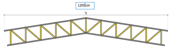
Truss width is entered. |
|
Left aligned 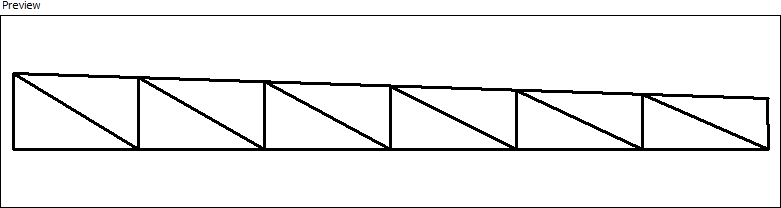
The left aligned option is marked so that the hill ridge is on the left edge. |
|
Centered 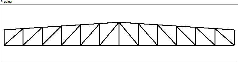
The centered option is marked so that the hill ridge is in the middle of the truss. |
|
Right aligned 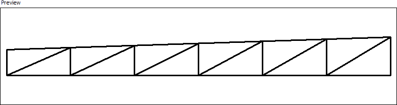
The right aligned option is marked so that the hill ridge is on the left edge. |
|
User defined 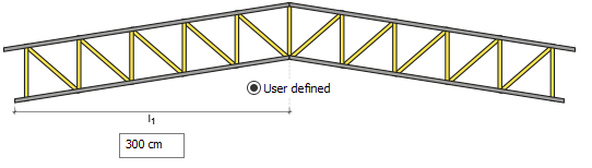
It is the value determining the height of the top of the trusses. |
|
Header division 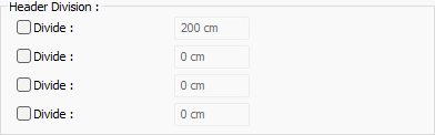
Divides the header of the truss at the entered distance. Divided in a maximum of 4 points. |
|
Footer division 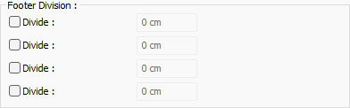
Divides the footer of the truss at the entered distance. Divided in a maximum of 4 points. |
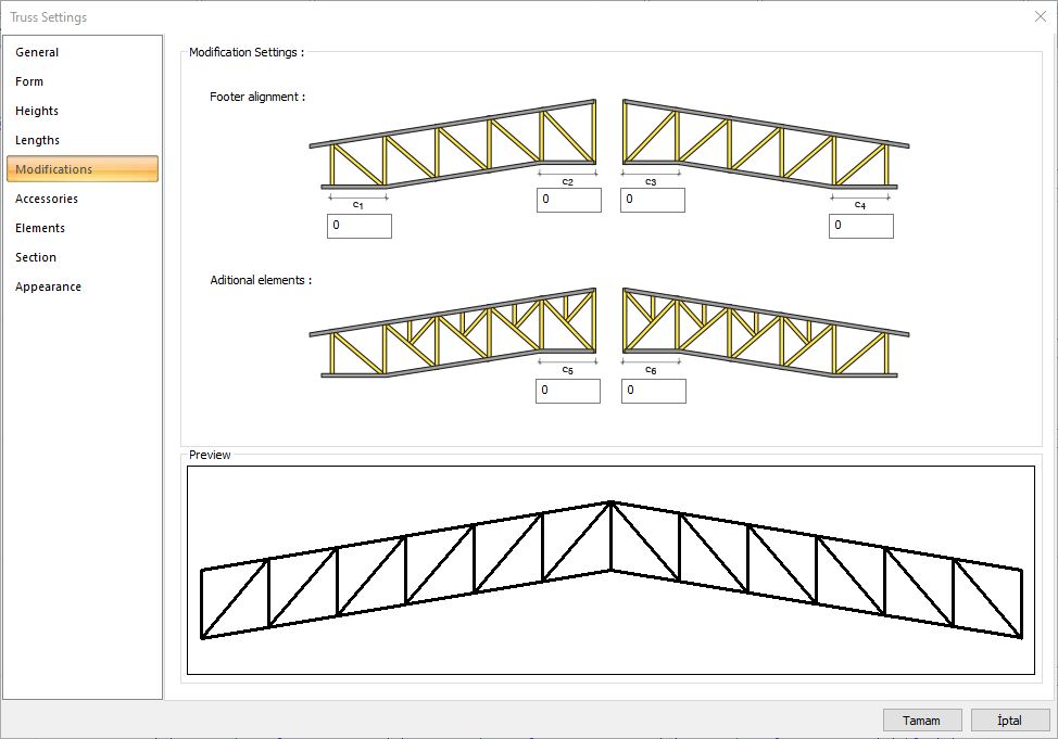
Modifications Tab
|
Specifications |
|---|
|
c1 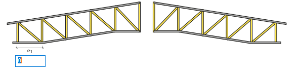
The footer placement value to be made on the left edge of the truss is entered. According to the entered value, a straight placement is made towards the right. |
|
c2 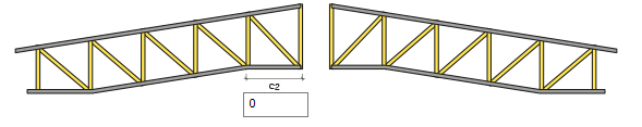
Enter the footer placement value to be made on the left side of the top ridge of the truss. According to the entered value, a straight placement is made towards the left. |
|
c3 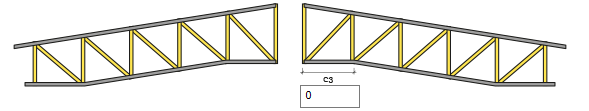
Enter the footer placement value to be made on the right side of the top ridge of the truss. According to the entered value, straight placement is made towards the right. |
|
c4 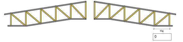
Enter the footer placement value to be made on the right edge of the truss. According to the entered value, a straight placement is made towards the left. |
|
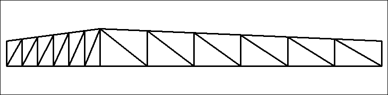
Preview 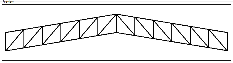
|
In the table below, examples of preview are given for the values entered in the modification settings.
|
When c1 and c4 are 2 
|
|
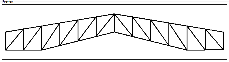
When c1, c2, c3 and c4 are 2 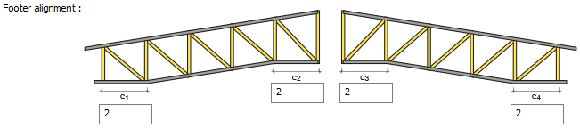
|
|
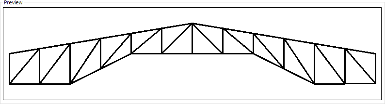
When c5 is 2 and c6 is 4 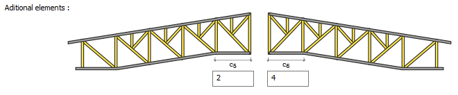
|
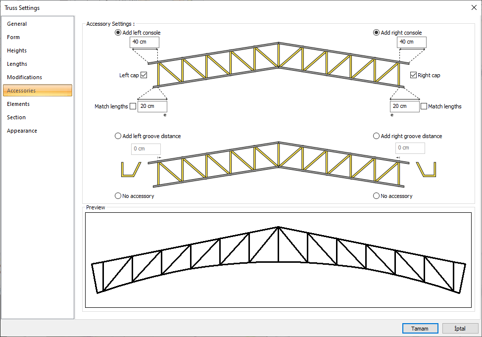
Accesiories Tab
|
Specifications |
|---|
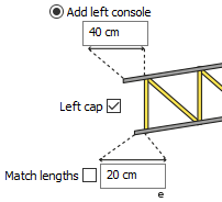
Console is added by giving different values to the upper left and lower headings of the scissors from the left console add section. By checking the Balance option, the value given to the subtitle is also applied to the header. The left cover option is marked and a cover is added to the end of the console. |
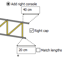
Console is added by giving different values to the upper right and lower headings of the scissors from the add right console section. By checking the Balance option, the value given to the subtitle is also applied to the header. The right cover option is marked and a cover is added to the end of the console. |
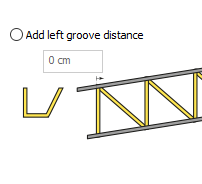
At the top nozzle, at the left end, is the distance value for the groove. The upper left end is taken in for the given value. |
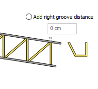
It is the distance value for the groove at the top head, right end. The upper right end is taken in for the given value. |
|
Console and/or groove distances are canceled. |
|
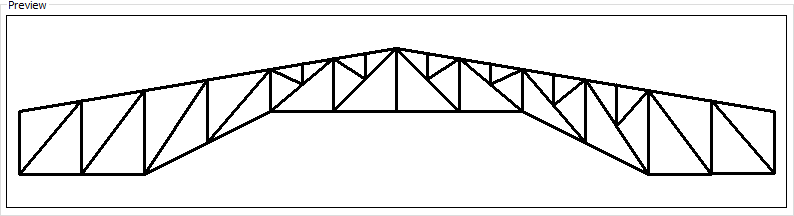
Preview 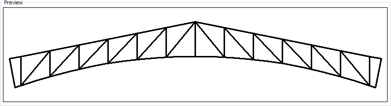
|
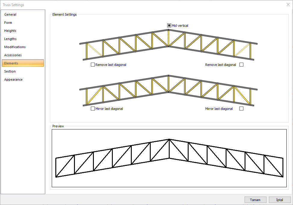
Elements Tab
|
Specifications |
|---|
|
Mid-vertical 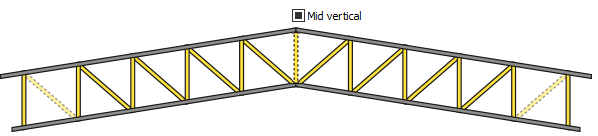
By unchecking the option, the central vertical element of the truss is removed. 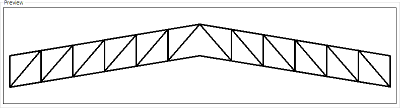
|
|
Remove last dioganal 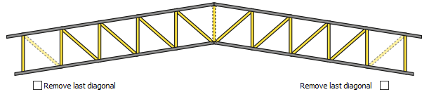
By checking the option, the last dioganal member of the truss is removed. 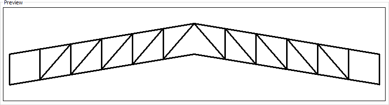
|
|
Mirror last diagonal 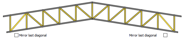
Checking the option, the direction of the truss is changed by taking the symmetry of the last dioganal member. 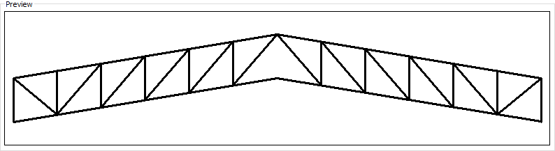
|
Section Tab
|
Specifications |
|---|
|
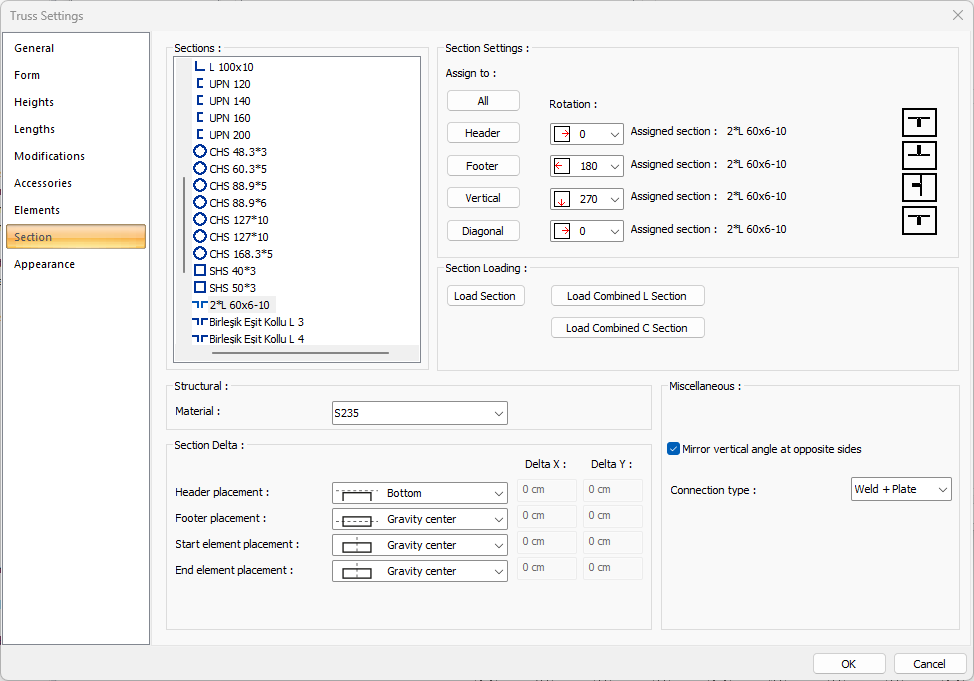
Sections 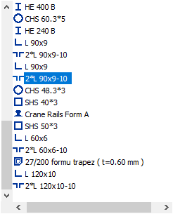
All sections with the project added are listed. The wanted truss section is selected from the list and assigned to the truss elements. A section not included in the list is added to the list by using the load section button. |
|
Section settings 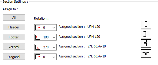
The truss elements of the section selected from the list from the profile section are assigned from this section. The selected section can be assigned to all truss elements by clicking the All button, and only the section can be assigned to that element by clicking one of the header, footer, vertical and diagonal buttons.
|
|
Section loading 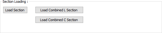
The Load Section button is used to add new sections to the sections in the section list .
|
|
Material 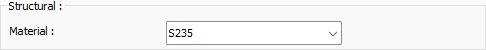
The material for the truss is selected. |
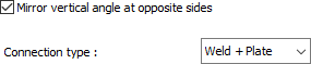

In case of using non-symmetrical profiles, this option is marked if the strut at the start and end of the scissors is desired to have different directions. 
|
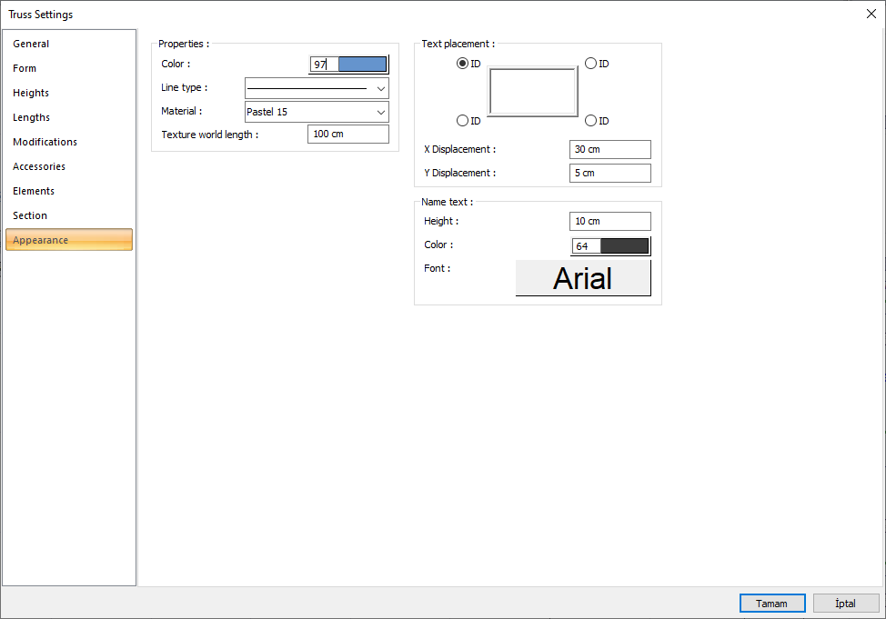
Apperance Tab
|
Specifications |
|---|
|
Color It is the color of truss edge lines. It scrolls on the color palette that is opened by clicking and holding down the left mouse button. The button is released when the desired color is reached. The color box turns into the selected color. |
|
Line type Line type of the line forming the truss is selected in the plan. Clicking the down arrow buttons to the right of the boxes opens the list of line types. From this list, the desired line type is selected by clicking with the left mouse button. |
|
Materiel In the solid model of the truss, the material to be covered is selected. The truss is covered with the selected material and displayed in the solid model like this. |
|
Texture world length Texture length is entered. For example; If 1 meter is entered, the selected material texture is taken as 1 meter and covered on the selected object. If the texture is thought to be in the form of a square, the object surfaces are covered with 1x1 textures arranged side by side. |
|
Text placement 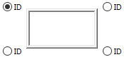
The location where the name of the truss will be written is determined according to the figure in the dialog. The program will place the name of the element according to the position chosen when the crosstab is created. |
|
Size X/Size Y X and Y coordinates are entered according to the upper right corner of the truss name. If the dimension X value is positive, the dimension text shifts to the left, if it is negative, it shifts to the right. If the dimension Y value is positive, the dimension text will scroll up, and if it is negative, it will scroll down. |
|
Name text 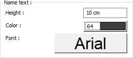
The height of the name of the truss is entered. The color box is slid over the color palette that is opened by clicking with the left mouse button and holding down the button. The button is released when the desired color is reached. The color box turns into the selected color. If clicked together with the Shift key, the pen thickness of the relevant color can be adjusted. If the button below is clicked, the Font Settings dialog opens. Column Name Text, font type is set from this dialog. |
Next Topic