
Symbols
Ag: Gross area
Ae: Effective net area
An: Net area
Agv: Gross shear area
Anv : Net shear area
Ant: Net tensile area
Fy: Specified yield stress of the type of steel being used, ksi (MPa)
Fu: Specified ultimate stress of the type of steel being used, ksi (MPa)
K: Twisting length coefficient
L: Element length between supported points
i: Radius of gyration
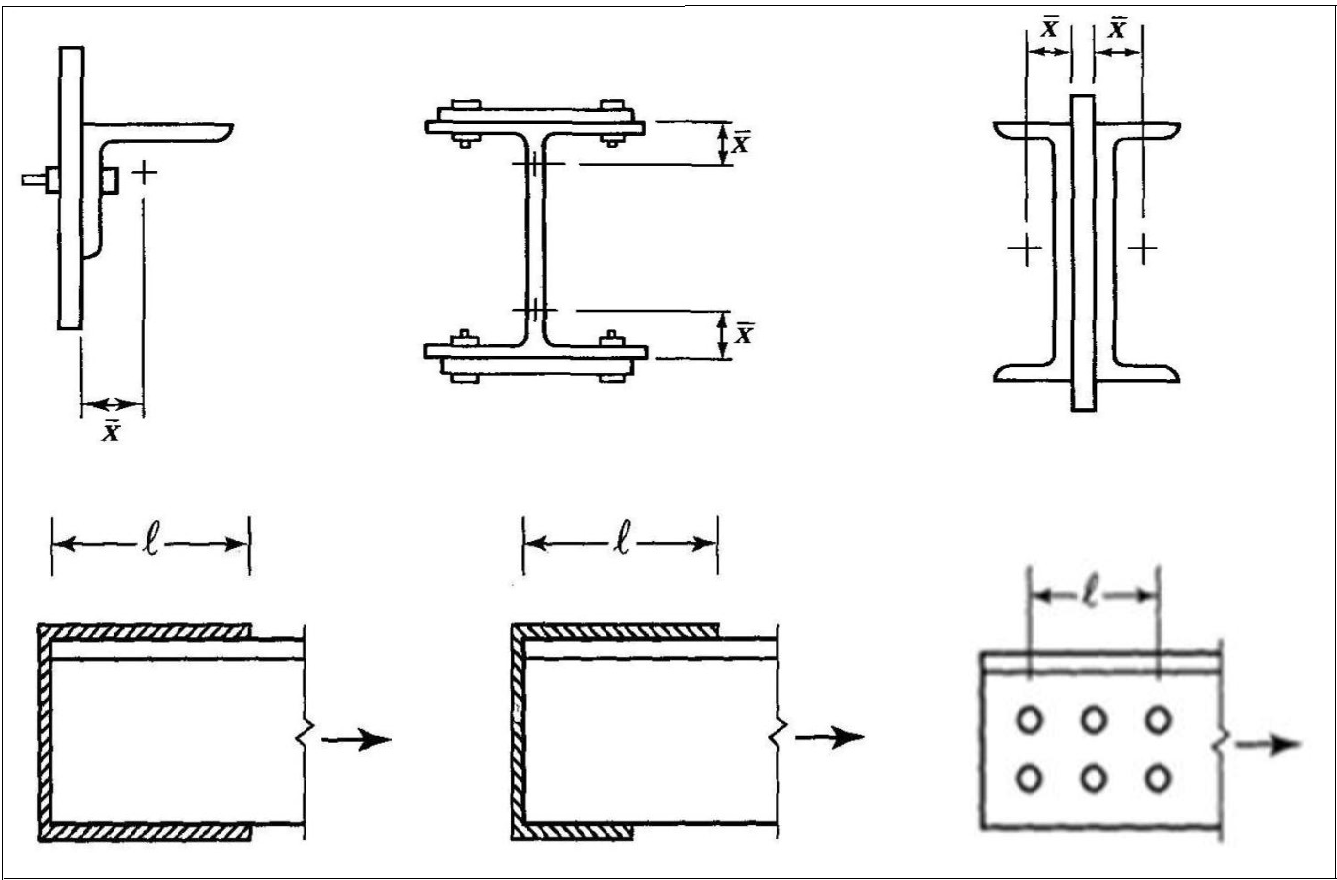
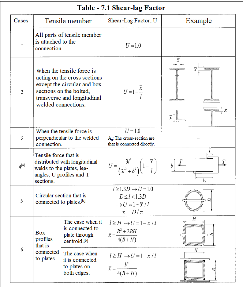
U: Non-uniform stress distribution coefficient
Ubs: A coefficient considering the distribution of tensile stresses
Tn: Design tensile strength
Strength of Truss Members Under Tensile Forces
-
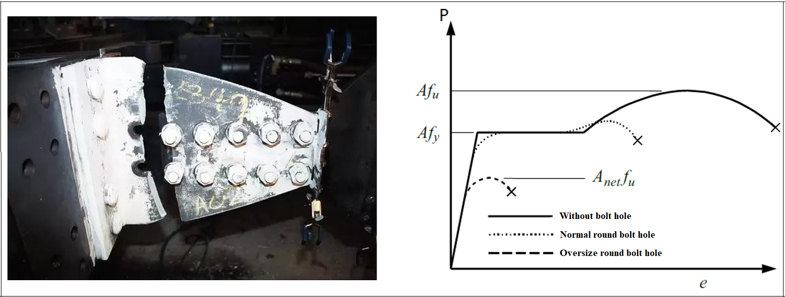
If axial tensile elements are used together with bolted joints, yield stress will be reached earlier in the areas where bolt holes are located. This situation will affect the strength computations made by using the load-displacement curve and assuming linear elastic.
-
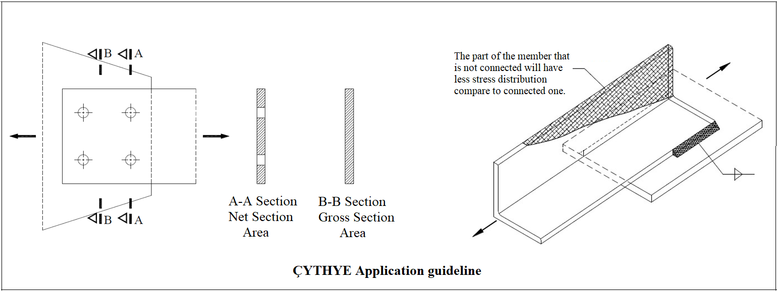
In bolted and welded joints of tensile members, because of the uneven distribution of load, the cross-sectional area operating in load transfer is not equal to the entire cross-section.
-
Since the L and U sections are used especially in the braces and are not connected with bolts or welding, a certain region that is called as the effective area works in load transfer. Due to this phenomenon called as 'Shear Lag' effect, the effective net area is used in the design of tensile members.
-
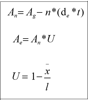
3 different areas are used in the strength calculation in tensile members:
-
Gross Area (Ag)
-
Net Area (Anet)
-
Effective Net Area (Ae)
-
Design with ÇYTHYE 2018
-
There are 3 different failure conditions in the members affected by the tensile force: Yielding Limit State, Rupture Limit State and Block Shear Limit State
-
The design tensile strength is taken as the minimum strength to be calculated according to the yield limit state, rupture limit state and block shear limit state of the member under axial tensile force. Block shear limit situation used in connections of tensile members is given in ÇYTHYE 2018 Section 13.4.3. Block break limit state is an additional check for connections.
-
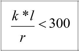
Tensile member slenderness should be controlled. In accordance with article 7.1.1 of the regulation, the slenderness ratio should be less than 300.
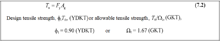
Yielding Limit State
-
The characteristic tensile strength Tn for the yielding limit state in tensile members is calculated by equation 7.2 using the gross cross-section area.
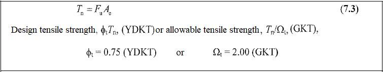
Rupture Limit State
-
The characteristic tensile strength Tn for the yielding limit state in tensile members is calculated by equation 7.3 using the net cross-section area.
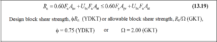
Block Shear Limit State
-
The characteristic block shear strength is calculated by equation 13.19, based on the yield and rupture limit states along the Rn shear surface or surfaces and tensile rupture limit state along the vertical tensile surface.
Related Topics