
Analysis, design and code requirements check results of punching in column (or shearwall) - slab connections in slabs without beam systems and raft foundations.
Location of the Column Drop Panel-Pedestal Reinforcements/Column Punching Dialog
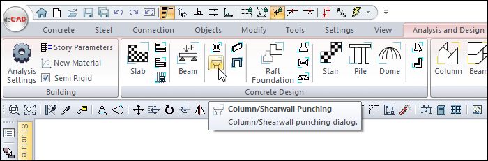
After the analysis, you can access it by clicking the Column/Shearwall Punching command under the ribbon menu Analysis and Design tab, Concrete Design heading.
Column Drop Panel-Pedestal Reinforcements/Column Punching Dialog General Features
|
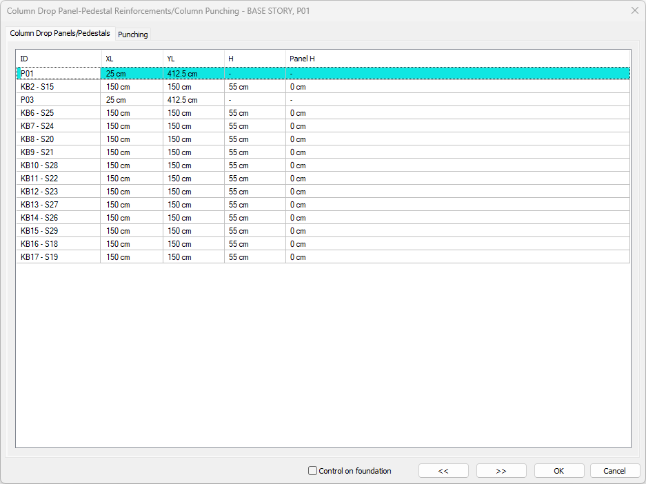
Summary Summary information about the line where the cursor is located is given in the name of the dialog in Solid, Name format. 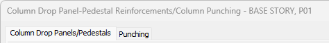
Example: BASE STORY, P01 |
|
Using the Shift key In this tab, you can select more than one row with the Shift key, enter a value by double-clicking on any cell whose value is open to change, and make that value apply to all selected rows. |
|
Using the Ctrl key The Ctrl key selects the in-between lines one by one. |
|
Control on foundation If checked, it displays the punching control. If unchecked, displays punching controls for tiles. |
|
Previous The cursor moves to the previous line. |
|
Next The cursor moves to the next line. |
|
OK Saves the changes made and closes the dialog. |
|
Cancel Closes the dialog without saving the changes made. |
Column Drop Panels/Pedestals Tab
|
Specifications |
|---|
|
ID 
The name of the column/shearwall in the plan. If the column/shearwall title is defined, it is written as the column/shearwall title - column/shearwall name. |
|
XL 
The column head is size X. If the header is not defined, it is the width of the column. Only width of the shearwall is shown. |
|
YL 
The column head is Y dimension. If the header is not defined, it is the width of the column. Only width of the shearwall is shown. |
|
H 
The value appears when the title is defined. It is the column head height. If the head is not in the defined punching control, the slab/raft thickness is taken into account. |
|
Panel H 
The thickness of the horizontal plate on the column header when the header is defined. |
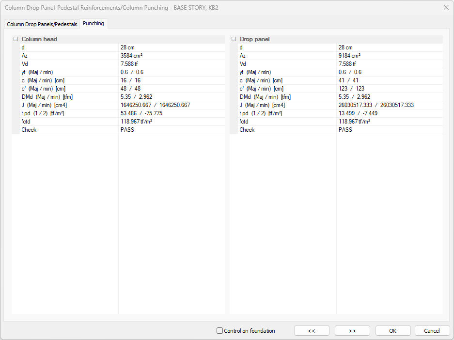
Punching Tab
|
Specifications |
|---|
|
d It refers to the useful height of the slab. It is the value obtained from the slab thickness with the concrete cover of the slab. |
|
Az Punching area. The slab useful height of the punching critical section is obtained by multiplying d.
Punching critical section (up) : It is the critical section calculated at d/2 distance from the column or wall surface. While calculating the punching perimeter, all of the slab gaps, corner or edge column-shearwall, polygon column situations are taken into account. |
|
Vd
Shear force based on punching calculation |
|
γf (Maj/min) It is the coefficient that reflects the bending effect in the punching calculation. The dimensions of the rectangular punching circumference are calculated as b1 in the considered loading direction and b2 in the perpendicular direction to the loading for major/minor axis, as shown in TBDY 2018 Equation 7.28. For circular columns, γf = 0.60 is used.circular columns, γf = 0.60 is used. |
|
c (maj/min) c (major) are the center of gravity values of the punching area in the direction of the moment considered, in the direction of the strong axis. c (minor) are the center of gravity values of the punching area in the direction of the moment considered, in the direction of the weak axis. |
|
c'(maj/min) c' (major) are the center of gravity values of the reverse punching area of the considered moment, in the direction of the strong axis. c' (minor) are the center of gravity values of the reverse punching area of the considered moment, in the direction of the weak axis. |
|
DMd (maj/min) DMd (major) is the value calculated on the strong axis of the column, under the combined effect of vertical loads and earthquake loads, and multiplied by the Excess of Strength Coefficient of the main design moments for the slab punching calculation. When calculating the punching stresses (τpd,1 and τpd,2), the bending moment values that occur under the joint effect of earthquake loads calculated considering the vertical loads and the Excess Strength Coefficient D are used. DMd (minor) is the value calculated on the weak axis of the column under the combined effect of vertical loads and earthquake loads, multiplied by the Excess of Strength Coefficient of the design moments that are the basis for the slab punching calculation. When calculating the punching stresses (τpd,1 and τpd,2), the bending moment values that occur under the joint effect of earthquake loads calculated considering the vertical loads and the Excess Strength Coefficient D are used. |
|
J (maj/min) J (major) is the sum of polar inertia and second moments in the strong axis of the surfaces forming the punching area (Az). The J value is calculated by considering the strong axis and the weak axis separately. J (minor) is the sum of polar inertia and second moments in the weak axis of the surfaces forming the punching area (Az). The J value is calculated by considering the strong axis and the weak axis separately. |
|
τpd, 1, τpd, 2 It represents the design-based punching stresses. Considering the effect of axial force and bending moments, the slab is the largest and smallest punching stresses. |
|
fctd Design tensile strength of concrete |
|
Check Specifies whether the stapling account is sufficient. |
Next Topic
Related Topics