
Stell Beam flexural design provisions are explained in detail under this title.
Symbols
Cb : The lateral-torsional buckling modification factor
Zx = Plastic section modulus about the x-axis, in.3 (mm3)
E: Modulus of elasticity of steel = 29,000 ksi (200 000 MPa)
Fy : Specified minimum yield stress of the type of steel being used, ksi
Its : Effective radius of inertia
J: Torsional constant
ho : Distance between the flange centroids, in. (mm)
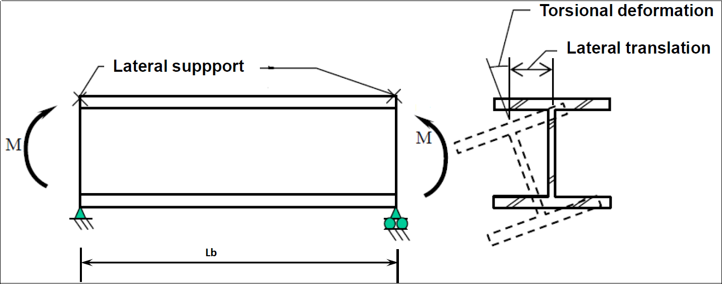
Lb : Length between points that are either braced against lateral displacement of the compression flange or braced against twist of the cross-section, in. (mm)
Lp : The limiting laterally unbraced length for the limit state of yielding, in. (mm)
Lr : The limiting unbraced length for the limit state of inelastic lateral-torsional
buckling, in. (mm),
Mn : The nominal flexural strength
Mp : Plastic bending moment
Sx : Elastic section modulus taken about the x-axis, in.3 (mm3)
Bending Member Definition
-
Members that are affected by bending moment around any of their principal axes. In the members with the effect of bending, the loads should act in the plane parallel to the principal axis passing through the shear center, or the member should be supported against torsion at the load impact points and supports.
-
The design flexural strength =
![]()
-
The allowable flexural strength =
![]()
'%3e%3cg transform='translate(167%2c0)'%3e%3cg transform='translate(-13%2c0)'%3e%3cg transform='translate(0%2c-47)'%3e%3cuse xlink:href='%23MJMATHI-3D5' x='0' y='0'%3e%3c/use%3e%3cuse transform='scale(0.707)' xlink:href='%23MJMATHI-62' x='843' y='-213'%3e%3c/use%3e%3cg transform='translate(1000%2c0)'%3e%3cuse xlink:href='%23MJMATHI-4D' x='0' y='0'%3e%3c/use%3e%3cuse transform='scale(0.707)' xlink:href='%23MJMATHI-6E' x='1372' y='-213'%3e%3c/use%3e%3c/g%3e%3c/g%3e%3c/g%3e%3c/g%3e%3c/g%3e%3c/svg%3e)
'%3e%3cg transform='translate(167%2c0)'%3e%3cg transform='translate(-13%2c0)'%3e%3cg transform='translate(0%2c-25)'%3e%3cuse xlink:href='%23MJMATHI-4D' x='0' y='0'%3e%3c/use%3e%3cuse transform='scale(0.707)' xlink:href='%23MJMATHI-6E' x='1372' y='-213'%3e%3c/use%3e%3cuse xlink:href='%23MJMAIN-2F' x='1495' y='0'%3e%3c/use%3e%3cg transform='translate(1995%2c0)'%3e%3cuse xlink:href='%23MJMAIN-3A9' x='0' y='0'%3e%3c/use%3e%3cuse transform='scale(0.707)' xlink:href='%23MJMATHI-62' x='1021' y='-213'%3e%3c/use%3e%3c/g%3e%3c/g%3e%3c/g%3e%3c/g%3e%3c/g%3e%3c/svg%3e)
'%3e%3cg transform='translate(167%2c0)'%3e%3cg transform='translate(-13%2c0)'%3e%3cg transform='translate(0%2c-25)'%3e%3cuse xlink:href='%23MJMATHI-3D5' x='0' y='0'%3e%3c/use%3e%3cuse transform='scale(0.707)' xlink:href='%23MJMATHI-62' x='843' y='-213'%3e%3c/use%3e%3cuse xlink:href='%23MJMAIN-3D' x='1277' y='0'%3e%3c/use%3e%3cg transform='translate(2334%2c0)'%3e%3cuse xlink:href='%23MJMAIN-30'%3e%3c/use%3e%3cuse xlink:href='%23MJMAIN-2E' x='500' y='0'%3e%3c/use%3e%3cuse xlink:href='%23MJMAIN-39' x='779' y='0'%3e%3c/use%3e%3cuse xlink:href='%23MJMAIN-30' x='1279' y='0'%3e%3c/use%3e%3c/g%3e%3cuse xlink:href='%23MJMAIN-28' x='4669' y='0'%3e%3c/use%3e%3cuse xlink:href='%23MJMATHI-4C' x='5059' y='0'%3e%3c/use%3e%3cuse xlink:href='%23MJMATHI-52' x='5740' y='0'%3e%3c/use%3e%3cuse xlink:href='%23MJMATHI-46' x='6500' y='0'%3e%3c/use%3e%3cuse xlink:href='%23MJMATHI-44' x='7249' y='0'%3e%3c/use%3e%3cuse xlink:href='%23MJMAIN-29' x='8078' y='0'%3e%3c/use%3e%3cg transform='translate(11245%2c0)'%3e%3cuse xlink:href='%23MJMAIN-3A9' x='0' y='0'%3e%3c/use%3e%3cuse transform='scale(0.707)' xlink:href='%23MJMATHI-62' x='1021' y='-213'%3e%3c/use%3e%3c/g%3e%3cuse xlink:href='%23MJMAIN-3D' x='12649' y='0'%3e%3c/use%3e%3cg transform='translate(13705%2c0)'%3e%3cuse xlink:href='%23MJMAIN-31'%3e%3c/use%3e%3cuse xlink:href='%23MJMAIN-2E' x='500' y='0'%3e%3c/use%3e%3cuse xlink:href='%23MJMAIN-36' x='779' y='0'%3e%3c/use%3e%3cuse xlink:href='%23MJMAIN-37' x='1279' y='0'%3e%3c/use%3e%3c/g%3e%3cuse xlink:href='%23MJMAIN-28' x='16041' y='0'%3e%3c/use%3e%3cuse xlink:href='%23MJMATHI-41' x='16430' y='0'%3e%3c/use%3e%3cuse xlink:href='%23MJMATHI-53' x='17181' y='0'%3e%3c/use%3e%3cuse xlink:href='%23MJMATHI-44' x='17826' y='0'%3e%3c/use%3e%3cuse xlink:href='%23MJMAIN-29' x='18655' y='0'%3e%3c/use%3e%3c/g%3e%3c/g%3e%3c/g%3e%3c/g%3e%3c/svg%3e)
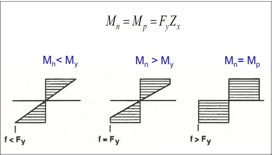
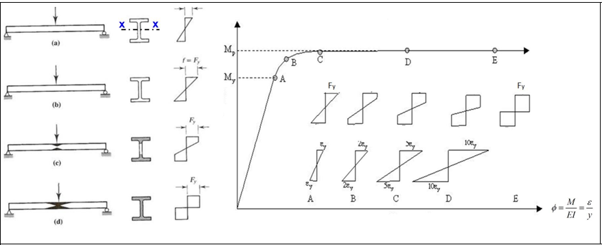
Yielding Limit State
-
It is a situation where the beam's cross-section is dimensioned to remain stable until it becomes plastic above the effect of bending if the local buckling of the compression flange and the lateral torsional buckling are prevented. In this case, the characteristic moment strength is considered equal to the plastic moment strength.
-
The yield moment is that the upper fiber of the section above the influence of the bending moment reaches the yield stress.
-
The plastic moment is the moment value when all fibers of the section above the effect of bending moment reach the yield stress.
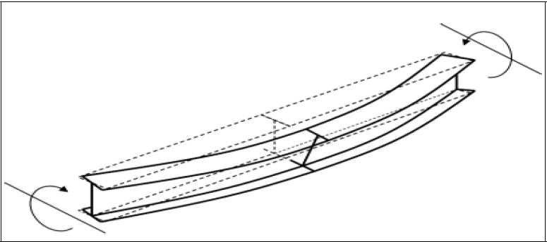
Lateral Torsional Buckling Limit State
-
The part of the beam in the compression flange area acts like an axially loaded compression frame. If the stability of the compression flange is not sufficient, the beam section cannot reach its full bending capacity. In this case, similar to the compression elements, global buckling or loss of stability in cross-sectional parts that may occur with local buckling determines the collapse limit state. This type of buckling of the compression flange is called lateral torsional buckling.
Design with AISC 360-16
Yielding Limit State
The characteristic bending moment strength Mn for the yield limit state is calculated by Equation F1-2.
'%3e%3cg transform='translate(167%2c0)'%3e%3cg transform='translate(-13%2c0)'%3e%3cg transform='translate(0%2c-3)'%3e%3cuse xlink:href='%23MJMATHI-4D' x='0' y='0'%3e%3c/use%3e%3cuse transform='scale(0.707)' xlink:href='%23MJMATHI-6E' x='1372' y='-213'%3e%3c/use%3e%3cuse xlink:href='%23MJMAIN-3D' x='1772' y='0'%3e%3c/use%3e%3cg transform='translate(2829%2c0)'%3e%3cuse xlink:href='%23MJMATHI-4D' x='0' y='0'%3e%3c/use%3e%3cuse transform='scale(0.707)' xlink:href='%23MJMATHI-70' x='1372' y='-213'%3e%3c/use%3e%3c/g%3e%3cuse xlink:href='%23MJMAIN-3D' x='4533' y='0'%3e%3c/use%3e%3cg transform='translate(5589%2c0)'%3e%3cuse xlink:href='%23MJMATHI-46' x='0' y='0'%3e%3c/use%3e%3cuse transform='scale(0.707)' xlink:href='%23MJMATHI-79' x='910' y='-213'%3e%3c/use%3e%3c/g%3e%3cg transform='translate(6685%2c0)'%3e%3cuse xlink:href='%23MJMATHI-5A' x='0' y='0'%3e%3c/use%3e%3cuse transform='scale(0.707)' xlink:href='%23MJMATHI-78' x='966' y='-213'%3e%3c/use%3e%3c/g%3e%3cuse xlink:href='%23MJMAIN-28' x='17873' y='0'%3e%3c/use%3e%3cuse xlink:href='%23MJMATHI-46' x='18262' y='0'%3e%3c/use%3e%3cuse xlink:href='%23MJMAIN-32' x='19012' y='0'%3e%3c/use%3e%3cuse xlink:href='%23MJMAIN-2212' x='19735' y='0'%3e%3c/use%3e%3cuse xlink:href='%23MJMAIN-31' x='20735' y='0'%3e%3c/use%3e%3cuse xlink:href='%23MJMAIN-29' x='21236' y='0'%3e%3c/use%3e%3c/g%3e%3c/g%3e%3c/g%3e%3c/g%3e%3c/svg%3e)
Lateral Torsional Buckling Limit State
For the lateral torsion buckling limit state, the characteristic bending moment strength for 3 different failure limit conditions, the laterally unsupported length of compression flange Mn, the change due to Lb, and the effect of the moment correction coefficient Cb are shown in the figure below.
-
If Lb ≤ Lp, this limit situation need not apply.
-
If Lp < Lb ≤ Lr, the nominal flexural strength, Mn, is calculated by Equation F2-2.
'%3e%3cg transform='translate(167%2c0)'%3e%3cg transform='translate(-13%2c0)'%3e%3cuse xlink:href='%23MJMATHI-4D' x='0' y='0'%3e%3c/use%3e%3cuse transform='scale(0.707)' xlink:href='%23MJMATHI-6E' x='1372' y='-213'%3e%3c/use%3e%3cuse xlink:href='%23MJMAIN-3D' x='1772' y='0'%3e%3c/use%3e%3cg transform='translate(2829%2c0)'%3e%3cuse xlink:href='%23MJMATHI-43' x='0' y='0'%3e%3c/use%3e%3cuse transform='scale(0.707)' xlink:href='%23MJMATHI-62' x='1011' y='-213'%3e%3c/use%3e%3c/g%3e%3cuse xlink:href='%23MJSZ4-5B' x='3948' y='-1'%3e%3c/use%3e%3cg transform='translate(4531%2c0)'%3e%3cuse xlink:href='%23MJMATHI-4D' x='0' y='0'%3e%3c/use%3e%3cuse transform='scale(0.707)' xlink:href='%23MJMATHI-70' x='1372' y='-213'%3e%3c/use%3e%3c/g%3e%3cuse xlink:href='%23MJMAIN-2212' x='6180' y='0'%3e%3c/use%3e%3cuse xlink:href='%23MJMAIN-28' x='7181' y='0'%3e%3c/use%3e%3cg transform='translate(7570%2c0)'%3e%3cuse xlink:href='%23MJMATHI-4D' x='0' y='0'%3e%3c/use%3e%3cuse transform='scale(0.707)' xlink:href='%23MJMATHI-70' x='1372' y='-213'%3e%3c/use%3e%3c/g%3e%3cuse xlink:href='%23MJMAIN-2212' x='9219' y='0'%3e%3c/use%3e%3cg transform='translate(10220%2c0)'%3e%3cuse xlink:href='%23MJMAIN-30'%3e%3c/use%3e%3cuse xlink:href='%23MJMAIN-2E' x='500' y='0'%3e%3c/use%3e%3cuse xlink:href='%23MJMAIN-37' x='779' y='0'%3e%3c/use%3e%3c/g%3e%3cg transform='translate(11499%2c0)'%3e%3cuse xlink:href='%23MJMATHI-46' x='0' y='0'%3e%3c/use%3e%3cuse transform='scale(0.707)' xlink:href='%23MJMATHI-79' x='910' y='-213'%3e%3c/use%3e%3c/g%3e%3cg transform='translate(12595%2c0)'%3e%3cuse xlink:href='%23MJMATHI-53' x='0' y='0'%3e%3c/use%3e%3cuse transform='scale(0.707)' xlink:href='%23MJMATHI-78' x='867' y='-213'%3e%3c/use%3e%3c/g%3e%3cuse xlink:href='%23MJMAIN-29' x='13713' y='0'%3e%3c/use%3e%3cuse xlink:href='%23MJSZ3-28' x='14102' y='-1'%3e%3c/use%3e%3cg transform='translate(14839%2c0)'%3e%3cg transform='translate(120%2c0)'%3e%3crect stroke='none' width='3581' height='60' x='0' y='220'%3e%3c/rect%3e%3cg transform='translate(67%2c781)'%3e%3cuse xlink:href='%23MJMATHI-4C' x='0' y='0'%3e%3c/use%3e%3cuse transform='scale(0.707)' xlink:href='%23MJMATHI-62' x='963' y='-213'%3e%3c/use%3e%3cuse xlink:href='%23MJMAIN-2212' x='1307' y='0'%3e%3c/use%3e%3cg transform='translate(2308%2c0)'%3e%3cuse xlink:href='%23MJMATHI-4C' x='0' y='0'%3e%3c/use%3e%3cuse transform='scale(0.707)' xlink:href='%23MJMATHI-70' x='963' y='-213'%3e%3c/use%3e%3c/g%3e%3c/g%3e%3cg transform='translate(60%2c-686)'%3e%3cuse xlink:href='%23MJMATHI-4C' x='0' y='0'%3e%3c/use%3e%3cuse transform='scale(0.707)' xlink:href='%23MJMATHI-72' x='963' y='-213'%3e%3c/use%3e%3cuse xlink:href='%23MJMAIN-2212' x='1322' y='0'%3e%3c/use%3e%3cg transform='translate(2323%2c0)'%3e%3cuse xlink:href='%23MJMATHI-4C' x='0' y='0'%3e%3c/use%3e%3cuse transform='scale(0.707)' xlink:href='%23MJMATHI-70' x='963' y='-213'%3e%3c/use%3e%3c/g%3e%3c/g%3e%3c/g%3e%3c/g%3e%3cuse xlink:href='%23MJSZ3-29' x='18660' y='-1'%3e%3c/use%3e%3cuse xlink:href='%23MJSZ4-5D' x='19397' y='-1'%3e%3c/use%3e%3cuse xlink:href='%23MJMAIN-2264' x='20258' y='0'%3e%3c/use%3e%3cg transform='translate(21314%2c0)'%3e%3cuse xlink:href='%23MJMATHI-4D' x='0' y='0'%3e%3c/use%3e%3cuse transform='scale(0.707)' xlink:href='%23MJMATHI-70' x='1372' y='-213'%3e%3c/use%3e%3c/g%3e%3cuse xlink:href='%23MJMAIN-28' x='32741' y='0'%3e%3c/use%3e%3cuse xlink:href='%23MJMATHI-46' x='33130' y='0'%3e%3c/use%3e%3cuse xlink:href='%23MJMAIN-32' x='33880' y='0'%3e%3c/use%3e%3cuse xlink:href='%23MJMAIN-2212' x='34602' y='0'%3e%3c/use%3e%3cuse xlink:href='%23MJMAIN-32' x='35603' y='0'%3e%3c/use%3e%3cuse xlink:href='%23MJMAIN-29' x='36104' y='0'%3e%3c/use%3e%3c/g%3e%3c/g%3e%3c/g%3e%3c/svg%3e)
-
If Lb > Lr, then nominal flexural strength, Mn, is determined by equation F2-3.
'%3e%3cg transform='translate(167%2c0)'%3e%3cg transform='translate(-13%2c0)'%3e%3cg transform='translate(0%2c-7)'%3e%3cuse xlink:href='%23MJMATHI-4D' x='0' y='0'%3e%3c/use%3e%3cuse transform='scale(0.707)' xlink:href='%23MJMATHI-6E' x='1372' y='-213'%3e%3c/use%3e%3cuse xlink:href='%23MJMAIN-3D' x='1772' y='0'%3e%3c/use%3e%3cg transform='translate(2829%2c0)'%3e%3cuse xlink:href='%23MJMATHI-46' x='0' y='0'%3e%3c/use%3e%3cg transform='translate(643%2c-150)'%3e%3cuse transform='scale(0.707)' xlink:href='%23MJMATHI-63' x='0' y='0'%3e%3c/use%3e%3cuse transform='scale(0.707)' xlink:href='%23MJMATHI-72' x='433' y='0'%3e%3c/use%3e%3c/g%3e%3c/g%3e%3cg transform='translate(4198%2c0)'%3e%3cuse xlink:href='%23MJMATHI-53' x='0' y='0'%3e%3c/use%3e%3cuse transform='scale(0.707)' xlink:href='%23MJMATHI-78' x='867' y='-213'%3e%3c/use%3e%3c/g%3e%3cuse xlink:href='%23MJMAIN-2264' x='5594' y='0'%3e%3c/use%3e%3cg transform='translate(6650%2c0)'%3e%3cuse xlink:href='%23MJMATHI-4D' x='0' y='0'%3e%3c/use%3e%3cuse transform='scale(0.707)' xlink:href='%23MJMATHI-70' x='1372' y='-213'%3e%3c/use%3e%3c/g%3e%3cuse xlink:href='%23MJMAIN-28' x='18077' y='0'%3e%3c/use%3e%3cuse xlink:href='%23MJMATHI-46' x='18466' y='0'%3e%3c/use%3e%3cuse xlink:href='%23MJMAIN-32' x='19216' y='0'%3e%3c/use%3e%3cuse xlink:href='%23MJMAIN-2212' x='19939' y='0'%3e%3c/use%3e%3cuse xlink:href='%23MJMAIN-33' x='20939' y='0'%3e%3c/use%3e%3cuse xlink:href='%23MJMAIN-29' x='21440' y='0'%3e%3c/use%3e%3c/g%3e%3c/g%3e%3c/g%3e%3c/g%3e%3c/svg%3e)
'%3e%3cg transform='translate(167%2c0)'%3e%3cg transform='translate(-13%2c0)'%3e%3cg transform='translate(0%2c18)'%3e%3cuse xlink:href='%23MJMATHI-4C' x='0' y='0'%3e%3c/use%3e%3cuse transform='scale(0.707)' xlink:href='%23MJMATHI-70' x='963' y='-213'%3e%3c/use%3e%3cuse xlink:href='%23MJMAIN-3D' x='1415' y='0'%3e%3c/use%3e%3cg transform='translate(2471%2c0)'%3e%3cuse xlink:href='%23MJMAIN-31'%3e%3c/use%3e%3cuse xlink:href='%23MJMAIN-2E' x='500' y='0'%3e%3c/use%3e%3cuse xlink:href='%23MJMAIN-37' x='779' y='0'%3e%3c/use%3e%3cuse xlink:href='%23MJMAIN-36' x='1279' y='0'%3e%3c/use%3e%3c/g%3e%3cg transform='translate(4251%2c0)'%3e%3cuse xlink:href='%23MJMATHI-72' x='0' y='0'%3e%3c/use%3e%3cuse transform='scale(0.707)' xlink:href='%23MJMATHI-79' x='638' y='-213'%3e%3c/use%3e%3c/g%3e%3cg transform='translate(5154%2c0)'%3e%3cuse xlink:href='%23MJSZ4-221A' x='0' y='-49'%3e%3c/use%3e%3crect stroke='none' width='1455' height='60' x='1000' y='1642'%3e%3c/rect%3e%3cg transform='translate(1000%2c0)'%3e%3cg transform='translate(120%2c0)'%3e%3crect stroke='none' width='1215' height='60' x='0' y='220'%3e%3c/rect%3e%3cuse xlink:href='%23MJMATHI-45' x='225' y='676'%3e%3c/use%3e%3cg transform='translate(60%2c-686)'%3e%3cuse xlink:href='%23MJMATHI-46' x='0' y='0'%3e%3c/use%3e%3cuse transform='scale(0.707)' xlink:href='%23MJMATHI-79' x='910' y='-213'%3e%3c/use%3e%3c/g%3e%3c/g%3e%3c/g%3e%3c/g%3e%3cuse xlink:href='%23MJMAIN-28' x='17610' y='0'%3e%3c/use%3e%3cuse xlink:href='%23MJMATHI-46' x='18000' y='0'%3e%3c/use%3e%3cuse xlink:href='%23MJMAIN-32' x='18749' y='0'%3e%3c/use%3e%3cuse xlink:href='%23MJMAIN-2212' x='19472' y='0'%3e%3c/use%3e%3cuse xlink:href='%23MJMAIN-35' x='20473' y='0'%3e%3c/use%3e%3cuse xlink:href='%23MJMAIN-29' x='20973' y='0'%3e%3c/use%3e%3c/g%3e%3c/g%3e%3c/g%3e%3c/g%3e%3c/svg%3e)
'%3e%3cg transform='translate(167%2c0)'%3e%3cg transform='translate(-13%2c0)'%3e%3cg transform='translate(0%2c-250)'%3e%3cuse xlink:href='%23MJMATHI-4C' x='0' y='0'%3e%3c/use%3e%3cuse transform='scale(0.707)' xlink:href='%23MJMATHI-72' x='963' y='-213'%3e%3c/use%3e%3cuse xlink:href='%23MJMAIN-3D' x='1378' y='0'%3e%3c/use%3e%3cg transform='translate(2434%2c0)'%3e%3cuse xlink:href='%23MJMAIN-31'%3e%3c/use%3e%3cuse xlink:href='%23MJMAIN-2E' x='500' y='0'%3e%3c/use%3e%3cuse xlink:href='%23MJMAIN-39' x='779' y='0'%3e%3c/use%3e%3cuse xlink:href='%23MJMAIN-35' x='1279' y='0'%3e%3c/use%3e%3c/g%3e%3cg transform='translate(4214%2c0)'%3e%3cuse xlink:href='%23MJMATHI-72' x='0' y='0'%3e%3c/use%3e%3cg transform='translate(451%2c-150)'%3e%3cuse transform='scale(0.707)' xlink:href='%23MJMATHI-74' x='0' y='0'%3e%3c/use%3e%3cuse transform='scale(0.707)' xlink:href='%23MJMATHI-73' x='361' y='0'%3e%3c/use%3e%3c/g%3e%3c/g%3e%3cg transform='translate(5353%2c0)'%3e%3cg transform='translate(120%2c0)'%3e%3crect stroke='none' width='2494' height='60' x='0' y='220'%3e%3c/rect%3e%3cuse xlink:href='%23MJMATHI-45' x='865' y='676'%3e%3c/use%3e%3cg transform='translate(60%2c-686)'%3e%3cuse xlink:href='%23MJMAIN-30'%3e%3c/use%3e%3cuse xlink:href='%23MJMAIN-2E' x='500' y='0'%3e%3c/use%3e%3cuse xlink:href='%23MJMAIN-37' x='779' y='0'%3e%3c/use%3e%3cg transform='translate(1279%2c0)'%3e%3cuse xlink:href='%23MJMATHI-46' x='0' y='0'%3e%3c/use%3e%3cuse transform='scale(0.707)' xlink:href='%23MJMATHI-79' x='910' y='-213'%3e%3c/use%3e%3c/g%3e%3c/g%3e%3c/g%3e%3c/g%3e%3cg transform='translate(8088%2c0)'%3e%3cg transform='translate(0%2c2076)'%3e%3cuse xlink:href='%23MJSZ4-E001' x='0' y='-606'%3e%3c/use%3e%3cg transform='translate(0%2c-1421.8732351236904) scale(1%2c1.359222420325384)'%3e%3cuse xlink:href='%23MJSZ4-E000'%3e%3c/use%3e%3c/g%3e%3cuse xlink:href='%23MJSZ4-23B7' x='0' y='-2329'%3e%3c/use%3e%3c/g%3e%3crect stroke='none' width='16811' height='60' x='1056' y='2016'%3e%3c/rect%3e%3cg transform='translate(1056%2c0)'%3e%3cg transform='translate(120%2c0)'%3e%3crect stroke='none' width='2258' height='60' x='0' y='220'%3e%3c/rect%3e%3cg transform='translate(595%2c676)'%3e%3cuse xlink:href='%23MJMATHI-4A' x='0' y='0'%3e%3c/use%3e%3cuse xlink:href='%23MJMATHI-63' x='633' y='0'%3e%3c/use%3e%3c/g%3e%3cg transform='translate(60%2c-700)'%3e%3cuse xlink:href='%23MJMATHI-53' x='0' y='0'%3e%3c/use%3e%3cuse transform='scale(0.707)' xlink:href='%23MJMATHI-78' x='867' y='-213'%3e%3c/use%3e%3cg transform='translate(1118%2c0)'%3e%3cuse xlink:href='%23MJMATHI-68' x='0' y='0'%3e%3c/use%3e%3cuse transform='scale(0.707)' xlink:href='%23MJMATHI-6F' x='815' y='-213'%3e%3c/use%3e%3c/g%3e%3c/g%3e%3c/g%3e%3cuse xlink:href='%23MJMAIN-2B' x='2720' y='0'%3e%3c/use%3e%3cg transform='translate(3721%2c0)'%3e%3cuse xlink:href='%23MJSZ4-221A' x='0' y='113'%3e%3c/use%3e%3crect stroke='none' width='12089' height='60' x='1000' y='1804'%3e%3c/rect%3e%3cg transform='translate(1000%2c0)'%3e%3cuse xlink:href='%23MJSZ3-28' x='0' y='-1'%3e%3c/use%3e%3cg transform='translate(736%2c0)'%3e%3cg transform='translate(120%2c0)'%3e%3crect stroke='none' width='2258' height='60' x='0' y='220'%3e%3c/rect%3e%3cg transform='translate(595%2c676)'%3e%3cuse xlink:href='%23MJMATHI-4A' x='0' y='0'%3e%3c/use%3e%3cuse xlink:href='%23MJMATHI-63' x='633' y='0'%3e%3c/use%3e%3c/g%3e%3cg transform='translate(60%2c-700)'%3e%3cuse xlink:href='%23MJMATHI-53' x='0' y='0'%3e%3c/use%3e%3cuse transform='scale(0.707)' xlink:href='%23MJMATHI-78' x='867' y='-213'%3e%3c/use%3e%3cg transform='translate(1118%2c0)'%3e%3cuse xlink:href='%23MJMATHI-68' x='0' y='0'%3e%3c/use%3e%3cuse transform='scale(0.707)' xlink:href='%23MJMATHI-6F' x='815' y='-213'%3e%3c/use%3e%3c/g%3e%3c/g%3e%3c/g%3e%3c/g%3e%3cg transform='translate(3234%2c0)'%3e%3cuse xlink:href='%23MJSZ3-29' x='0' y='-1'%3e%3c/use%3e%3cuse transform='scale(0.707)' xlink:href='%23MJMAIN-32' x='1041' y='1665'%3e%3c/use%3e%3c/g%3e%3cuse xlink:href='%23MJMAIN-2B' x='4647' y='0'%3e%3c/use%3e%3cg transform='translate(5647%2c0)'%3e%3cuse xlink:href='%23MJMAIN-36'%3e%3c/use%3e%3cuse xlink:href='%23MJMAIN-2E' x='500' y='0'%3e%3c/use%3e%3cuse xlink:href='%23MJMAIN-37' x='779' y='0'%3e%3c/use%3e%3cuse xlink:href='%23MJMAIN-36' x='1279' y='0'%3e%3c/use%3e%3c/g%3e%3cuse xlink:href='%23MJSZ3-28' x='7427' y='-1'%3e%3c/use%3e%3cg transform='translate(8164%2c0)'%3e%3cg transform='translate(120%2c0)'%3e%3crect stroke='none' width='2494' height='60' x='0' y='220'%3e%3c/rect%3e%3cg transform='translate(60%2c789)'%3e%3cuse xlink:href='%23MJMAIN-30'%3e%3c/use%3e%3cuse xlink:href='%23MJMAIN-2E' x='500' y='0'%3e%3c/use%3e%3cuse xlink:href='%23MJMAIN-37' x='779' y='0'%3e%3c/use%3e%3cg transform='translate(1279%2c0)'%3e%3cuse xlink:href='%23MJMATHI-46' x='0' y='0'%3e%3c/use%3e%3cuse transform='scale(0.707)' xlink:href='%23MJMATHI-79' x='910' y='-213'%3e%3c/use%3e%3c/g%3e%3c/g%3e%3cuse xlink:href='%23MJMATHI-45' x='865' y='-686'%3e%3c/use%3e%3c/g%3e%3c/g%3e%3cg transform='translate(10899%2c0)'%3e%3cuse xlink:href='%23MJSZ3-29' x='0' y='-1'%3e%3c/use%3e%3cuse transform='scale(0.707)' xlink:href='%23MJMAIN-32' x='1041' y='1665'%3e%3c/use%3e%3c/g%3e%3c/g%3e%3c/g%3e%3c/g%3e%3c/g%3e%3cuse xlink:href='%23MJMAIN-28' x='35956' y='0'%3e%3c/use%3e%3cuse xlink:href='%23MJMATHI-46' x='36345' y='0'%3e%3c/use%3e%3cuse xlink:href='%23MJMAIN-32' x='37095' y='0'%3e%3c/use%3e%3cuse xlink:href='%23MJMAIN-2212' x='37818' y='0'%3e%3c/use%3e%3cuse xlink:href='%23MJMAIN-36' x='38818' y='0'%3e%3c/use%3e%3cuse xlink:href='%23MJMAIN-29' x='39319' y='0'%3e%3c/use%3e%3c/g%3e%3c/g%3e%3c/g%3e%3c/g%3e%3c/svg%3e)
'%3e%3cg transform='translate(167%2c0)'%3e%3cg transform='translate(-13%2c0)'%3e%3cg transform='translate(0%2c-199)'%3e%3cuse xlink:href='%23MJMATHI-72' x='0' y='0'%3e%3c/use%3e%3cuse transform='scale(0.707)' xlink:href='%23MJMAIN-32' x='638' y='488'%3e%3c/use%3e%3cg transform='translate(451%2c-279)'%3e%3cuse transform='scale(0.707)' xlink:href='%23MJMATHI-74' x='0' y='0'%3e%3c/use%3e%3cuse transform='scale(0.707)' xlink:href='%23MJMATHI-73' x='361' y='0'%3e%3c/use%3e%3c/g%3e%3cuse xlink:href='%23MJMAIN-3D' x='1416' y='0'%3e%3c/use%3e%3cg transform='translate(2473%2c0)'%3e%3cg transform='translate(120%2c0)'%3e%3crect stroke='none' width='3334' height='60' x='0' y='220'%3e%3c/rect%3e%3cg transform='translate(60%2c875)'%3e%3cuse xlink:href='%23MJSZ1-221A' x='0' y='-31'%3e%3c/use%3e%3crect stroke='none' width='2214' height='60' x='1000' y='760'%3e%3c/rect%3e%3cg transform='translate(1000%2c0)'%3e%3cuse xlink:href='%23MJMATHI-49' x='0' y='0'%3e%3c/use%3e%3cuse transform='scale(0.707)' xlink:href='%23MJMATHI-79' x='622' y='-213'%3e%3c/use%3e%3cg transform='translate(892%2c0)'%3e%3cuse xlink:href='%23MJMATHI-43' x='0' y='0'%3e%3c/use%3e%3cuse transform='scale(0.707)' xlink:href='%23MJMATHI-77' x='1011' y='-213'%3e%3c/use%3e%3c/g%3e%3c/g%3e%3c/g%3e%3cg transform='translate(1108%2c-700)'%3e%3cuse xlink:href='%23MJMATHI-53' x='0' y='0'%3e%3c/use%3e%3cuse transform='scale(0.707)' xlink:href='%23MJMATHI-78' x='867' y='-213'%3e%3c/use%3e%3c/g%3e%3c/g%3e%3c/g%3e%3cuse xlink:href='%23MJMAIN-28' x='16048' y='0'%3e%3c/use%3e%3cuse xlink:href='%23MJMATHI-46' x='16437' y='0'%3e%3c/use%3e%3cuse xlink:href='%23MJMAIN-32' x='17187' y='0'%3e%3c/use%3e%3cuse xlink:href='%23MJMAIN-2212' x='17909' y='0'%3e%3c/use%3e%3cuse xlink:href='%23MJMAIN-37' x='18910' y='0'%3e%3c/use%3e%3cuse xlink:href='%23MJMAIN-29' x='19411' y='0'%3e%3c/use%3e%3c/g%3e%3c/g%3e%3c/g%3e%3c/g%3e%3c/svg%3e)
-
For doubly symmetric I-shapes,
![]()
-
For channels
![]()
'%3e%3cg transform='translate(167%2c0)'%3e%3cg transform='translate(-13%2c0)'%3e%3cg transform='translate(0%2c-25)'%3e%3cuse xlink:href='%23MJMATHI-63' x='0' y='0'%3e%3c/use%3e%3cuse xlink:href='%23MJMAIN-3D' x='711' y='0'%3e%3c/use%3e%3cuse xlink:href='%23MJMAIN-31' x='1767' y='0'%3e%3c/use%3e%3cuse xlink:href='%23MJMAIN-28' x='12268' y='0'%3e%3c/use%3e%3cuse xlink:href='%23MJMATHI-46' x='12657' y='0'%3e%3c/use%3e%3cuse xlink:href='%23MJMAIN-32' x='13407' y='0'%3e%3c/use%3e%3cuse xlink:href='%23MJMAIN-2212' x='14129' y='0'%3e%3c/use%3e%3cuse xlink:href='%23MJMAIN-38' x='15130' y='0'%3e%3c/use%3e%3cuse xlink:href='%23MJMATHI-61' x='15630' y='0'%3e%3c/use%3e%3cuse xlink:href='%23MJMAIN-29' x='16160' y='0'%3e%3c/use%3e%3c/g%3e%3c/g%3e%3c/g%3e%3c/g%3e%3c/svg%3e)
'%3e%3cg transform='translate(167%2c0)'%3e%3cg transform='translate(-13%2c0)'%3e%3cg transform='translate(0%2c-102)'%3e%3cuse xlink:href='%23MJMATHI-63' x='0' y='0'%3e%3c/use%3e%3cuse xlink:href='%23MJMAIN-3D' x='711' y='0'%3e%3c/use%3e%3cg transform='translate(1767%2c0)'%3e%3cg transform='translate(120%2c0)'%3e%3crect stroke='none' width='2404' height='60' x='0' y='220'%3e%3c/rect%3e%3cg transform='translate(60%2c676)'%3e%3cuse xlink:href='%23MJMATHI-68' x='0' y='0'%3e%3c/use%3e%3cuse xlink:href='%23MJMAIN-2212' x='798' y='0'%3e%3c/use%3e%3cuse xlink:href='%23MJMATHI-6F' x='1799' y='0'%3e%3c/use%3e%3c/g%3e%3cuse xlink:href='%23MJMAIN-32' x='952' y='-686'%3e%3c/use%3e%3c/g%3e%3c/g%3e%3cg transform='translate(4412%2c0)'%3e%3cuse xlink:href='%23MJSZ4-221A' x='0' y='71'%3e%3c/use%3e%3crect stroke='none' width='1682' height='60' x='1000' y='1762'%3e%3c/rect%3e%3cg transform='translate(1000%2c0)'%3e%3cg transform='translate(120%2c0)'%3e%3crect stroke='none' width='1442' height='60' x='0' y='220'%3e%3c/rect%3e%3cg transform='translate(274%2c789)'%3e%3cuse xlink:href='%23MJMATHI-49' x='0' y='0'%3e%3c/use%3e%3cuse transform='scale(0.707)' xlink:href='%23MJMATHI-79' x='622' y='-213'%3e%3c/use%3e%3c/g%3e%3cg transform='translate(60%2c-700)'%3e%3cuse xlink:href='%23MJMATHI-43' x='0' y='0'%3e%3c/use%3e%3cuse transform='scale(0.707)' xlink:href='%23MJMATHI-77' x='1011' y='-213'%3e%3c/use%3e%3c/g%3e%3c/g%3e%3c/g%3e%3c/g%3e%3cuse xlink:href='%23MJMAIN-28' x='17095' y='0'%3e%3c/use%3e%3cuse xlink:href='%23MJMATHI-46' x='17484' y='0'%3e%3c/use%3e%3cuse xlink:href='%23MJMAIN-32' x='18234' y='0'%3e%3c/use%3e%3cuse xlink:href='%23MJMAIN-2212' x='18956' y='0'%3e%3c/use%3e%3cuse xlink:href='%23MJMAIN-38' x='19957' y='0'%3e%3c/use%3e%3cuse xlink:href='%23MJMATHI-62' x='20458' y='0'%3e%3c/use%3e%3cuse xlink:href='%23MJMAIN-29' x='20887' y='0'%3e%3c/use%3e%3c/g%3e%3c/g%3e%3c/g%3e%3c/g%3e%3c/svg%3e)
Cb : It is the positive contribution of bending moment propagation along the length between the points supported by the lateral stability connection in the case of the lateral torsional buckling limit.
'%3e%3cg transform='translate(167%2c0)'%3e%3cg transform='translate(-13%2c0)'%3e%3cg transform='translate(0%2c-3)'%3e%3cuse xlink:href='%23MJMATHI-43' x='0' y='0'%3e%3c/use%3e%3cuse transform='scale(0.707)' xlink:href='%23MJMATHI-62' x='1011' y='-213'%3e%3c/use%3e%3cuse xlink:href='%23MJMAIN-3D' x='1396' y='0'%3e%3c/use%3e%3cg transform='translate(2453%2c0)'%3e%3cg transform='translate(120%2c0)'%3e%3crect stroke='none' width='13857' height='60' x='0' y='220'%3e%3c/rect%3e%3cg transform='translate(4803%2c676)'%3e%3cuse xlink:href='%23MJMAIN-31'%3e%3c/use%3e%3cuse xlink:href='%23MJMAIN-32' x='500' y='0'%3e%3c/use%3e%3cuse xlink:href='%23MJMAIN-2E' x='1001' y='0'%3e%3c/use%3e%3cuse xlink:href='%23MJMAIN-35' x='1279' y='0'%3e%3c/use%3e%3cg transform='translate(1780%2c0)'%3e%3cuse xlink:href='%23MJMATHI-4D' x='0' y='0'%3e%3c/use%3e%3cg transform='translate(970%2c-150)'%3e%3cuse transform='scale(0.707)' xlink:href='%23MJMATHI-6D' x='0' y='0'%3e%3c/use%3e%3cuse transform='scale(0.707)' xlink:href='%23MJMATHI-61' x='878' y='0'%3e%3c/use%3e%3cuse transform='scale(0.707)' xlink:href='%23MJMATHI-78' x='1408' y='0'%3e%3c/use%3e%3c/g%3e%3c/g%3e%3c/g%3e%3cg transform='translate(60%2c-686)'%3e%3cuse xlink:href='%23MJMAIN-32'%3e%3c/use%3e%3cuse xlink:href='%23MJMAIN-2E' x='500' y='0'%3e%3c/use%3e%3cuse xlink:href='%23MJMAIN-35' x='779' y='0'%3e%3c/use%3e%3cg transform='translate(1279%2c0)'%3e%3cuse xlink:href='%23MJMATHI-4D' x='0' y='0'%3e%3c/use%3e%3cg transform='translate(970%2c-150)'%3e%3cuse transform='scale(0.707)' xlink:href='%23MJMATHI-6D' x='0' y='0'%3e%3c/use%3e%3cuse transform='scale(0.707)' xlink:href='%23MJMATHI-61' x='878' y='0'%3e%3c/use%3e%3cuse transform='scale(0.707)' xlink:href='%23MJMATHI-78' x='1408' y='0'%3e%3c/use%3e%3c/g%3e%3c/g%3e%3cuse xlink:href='%23MJMAIN-2B' x='3972' y='0'%3e%3c/use%3e%3cuse xlink:href='%23MJMAIN-33' x='4973' y='0'%3e%3c/use%3e%3cg transform='translate(5473%2c0)'%3e%3cuse xlink:href='%23MJMATHI-4D' x='0' y='0'%3e%3c/use%3e%3cuse transform='scale(0.707)' xlink:href='%23MJMATHI-41' x='1372' y='-230'%3e%3c/use%3e%3c/g%3e%3cuse xlink:href='%23MJMAIN-2B' x='7297' y='0'%3e%3c/use%3e%3cuse xlink:href='%23MJMAIN-34' x='8297' y='0'%3e%3c/use%3e%3cg transform='translate(8798%2c0)'%3e%3cuse xlink:href='%23MJMATHI-4D' x='0' y='0'%3e%3c/use%3e%3cuse transform='scale(0.707)' xlink:href='%23MJMATHI-42' x='1372' y='-213'%3e%3c/use%3e%3c/g%3e%3cuse xlink:href='%23MJMAIN-2B' x='10628' y='0'%3e%3c/use%3e%3cuse xlink:href='%23MJMAIN-33' x='11628' y='0'%3e%3c/use%3e%3cg transform='translate(12129%2c0)'%3e%3cuse xlink:href='%23MJMATHI-4D' x='0' y='0'%3e%3c/use%3e%3cuse transform='scale(0.707)' xlink:href='%23MJMATHI-43' x='1372' y='-219'%3e%3c/use%3e%3c/g%3e%3c/g%3e%3c/g%3e%3c/g%3e%3cuse xlink:href='%23MJMAIN-28' x='26551' y='0'%3e%3c/use%3e%3cuse xlink:href='%23MJMATHI-46' x='26940' y='0'%3e%3c/use%3e%3cuse xlink:href='%23MJMAIN-31' x='27690' y='0'%3e%3c/use%3e%3cuse xlink:href='%23MJMAIN-2212' x='28412' y='0'%3e%3c/use%3e%3cuse xlink:href='%23MJMAIN-31' x='29413' y='0'%3e%3c/use%3e%3cuse xlink:href='%23MJMAIN-29' x='29913' y='0'%3e%3c/use%3e%3c/g%3e%3c/g%3e%3c/g%3e%3c/g%3e%3c/svg%3e)
Design of Members for Combined Forces
-
It is the strength calculation made by considering the combined stresses created in the elements above bending and axial force.
-
Account details are available at Design of Steel Columns for Combined Forces per AISC 360-16.