
-
Transverse reinforcement with a diameter smaller than ϕ8 will not be used in the confinement areas and the distance of the first stirrup to the column face will be at most 50 mm.
-
Unless a more unfavorable value is obtained according to 7.4.5.3 , the condition that stirrup spacing does not exceed 1/4 of the effective height of the beam, eight times the smallest longitudinal reinforcement diameter and 150 mm is automatically applied.
-
Except for the coiling zone, the transverse reinforcement conditions given in TS 500 are complied with. The stirrup arms are automatically arranged perpendicular to the beam axis so that the spacing does not exceed 350 mm.
ICONS
ϕ = Rebar diameter
The region that is twice the height of the beam from the column surface in beam supports is called the Confinement Zone . Throughout this zone, special seismic hoops defined in TBDY Section 7.2.8 are used. It is not allowed to use reinforcement with a rebar diameter less than bölgeler8 in the confinement areas and the first stirrup of the confinement zone is placed 50 mm from the column face.
Section 7.4.5.3 TBDY recited in Shear Safety of beams required amount of transverse reinforcement section is calculated. However, asstated in 7.4.4 , stirrup spacing should not exceed 1/4 of the beam height, eight times the diameter of the smallest longitudinal reinforcement and 150 mm. Considering these two situations, the transverse reinforcements of the beams are placed automatically.
The conditions given in TS 500 are applied except for the coiling areas and the stirrup arms spacing perpendicular to the beam axis are not allowed to exceed 350 mm.
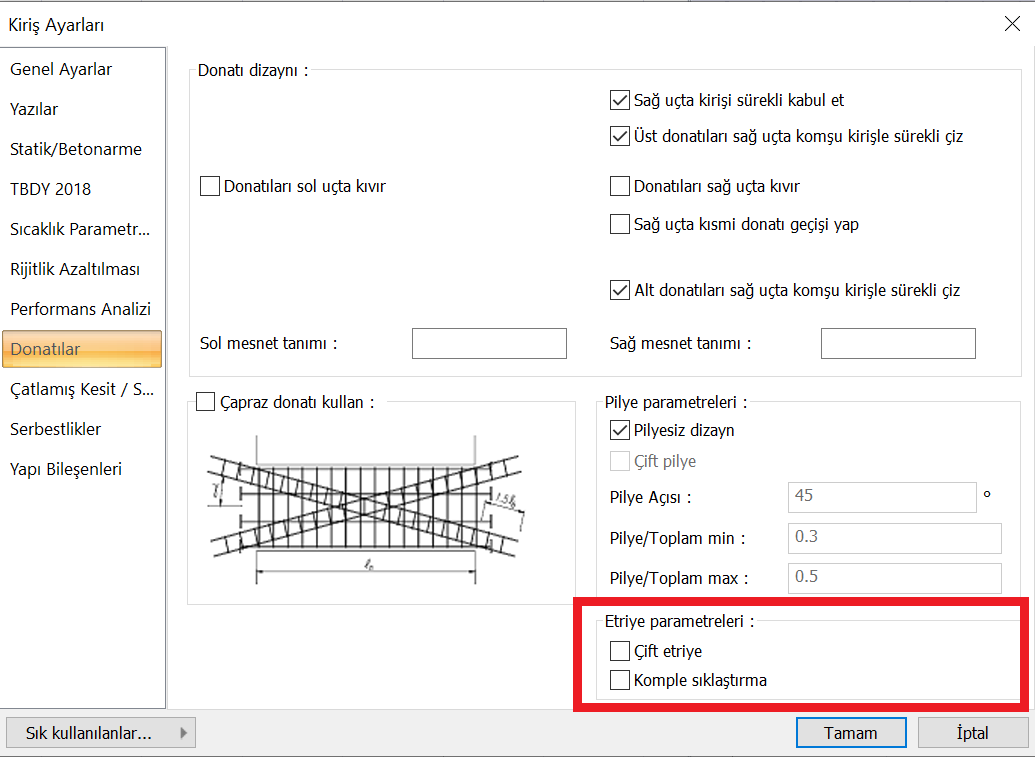
When necessary, there are also double stirrups and complete clamping options in accordance with TBDY 7.4.4 . Double stirrup and complete clamping options are shown in the picture below in the "Accessories" tab of the beam settings .
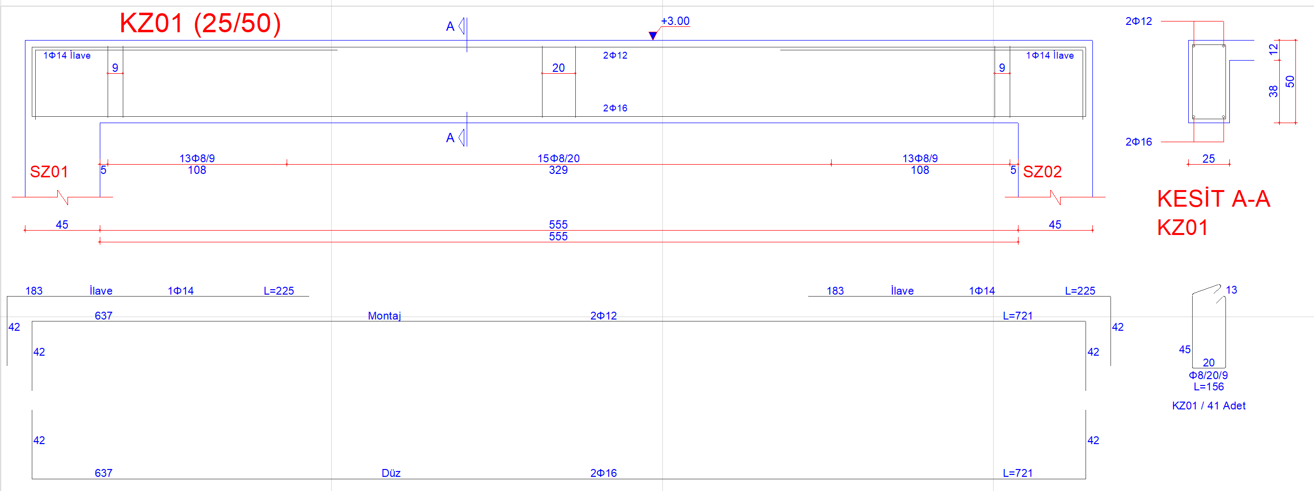
An arranged view of the transverse reinforcement for the regions outside the Confinement Zone and the confinement zone in accordance with TBDY 7.4.4 is given in the sample picture below.
Special earthquake hoops and crossties
Special seismic hoops and crossties defined in 7.2.8 are used along the entire beam .
The conditions required to be met by special earthquake hoops and crossties are given in Figure 7.1 .
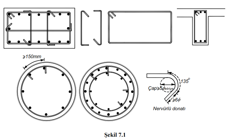
135 degree curved hooks are made at both ends of special earthquake hoops . For 135 degree bent hooks, ϕ is taken at least 5ϕ to show the diameter of the transverse reinforcement. The end straight length of the hooks is not taken less than 6ϕ and 80 mm in ribbed bars, starting from the final tangent point in the fold ( Figure 7.1 ).
Special seismic hoops will grasp the longitudinal reinforcement from the outside and the hooks are closed around the same longitudinal reinforcement. The diameter and spacing of special earthquake crossties are taken the same as the diameter and spacing of stirrups. The crossties are prepared at both ends in an order that will necessarily surround the longitudinal reinforcements and the outer stirrup.
Next Topic