
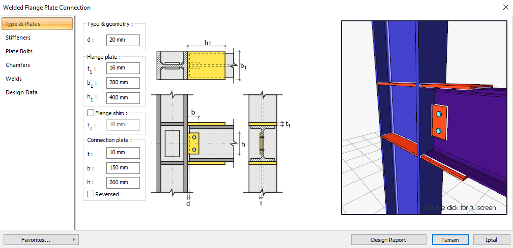
The Welded Flange Plate Connection is formed with butt welded welded head plates with cotton penetration to the column head and corner welded to the beam head. Body plate bolt control, welding control, plate control and connection application limits control are made automatically according to the placement of the elements of the connection. Welded Flange Plate Connection design is made automatically according to the Design, Calculation and Construction Principles of Steel Structures (ÇYTHYEDY) or AISC 360-16 regulations and a connection report is created.
In the calculation of the Welded Flange Plate Connection, the header plate and slip plate weld thickness, slip plate column head weld thickness, continuity plate - column head and body weld thickness are checked under geometry control. Head plate weld strength, header plate tensile failure, block slip at beam head, pressure plate leakage, slip plate weld strength, shear plate beam body strength, body plate shear failure, body plate bending yield, column panel region slippage are checked.
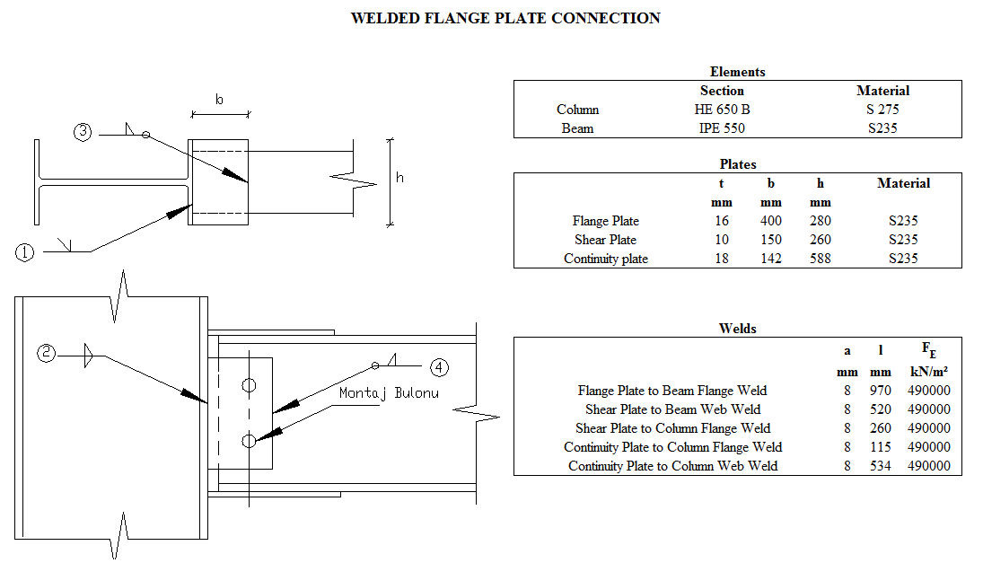
Connection Geometry
Geometry Checks
Flange Plate to Beam Flange Weld Size
|
|
|
|
|
|
|
6 mm |
|
√ |
|
|
4 mm |
Table 13.4 |
√ |
Shear Plate to Beam Web Weld Size
|
|
|
|
|
|
|
6 mm |
|
√ |
|
|
3.5 mm |
Table 13.4 |
√ |
Shear Plate to Column Flange Weld Size
|
|
|
|
|
|
|
6 mm |
|
√ |
|
|
3.5 mm |
Table 13.4 |
√ |
Continuity Plate to Column Flange Weld Size
|
|
|
|
|
|
|
6 mm |
|
√ |
|
|
4 mm |
Table 13.4 |
√ |
Continuity Plate to Column Web Weld Size
|
|
|
|
|
|
|
6 mm |
|
√ |
|
|
4 mm |
Table 13.4 |
√ |
Strength Checks
Flange Plate to Beam Flange Weld Strength
|
|
520 mm |
|
|
|
280 mm |
|
|
|
490 N/mm2 |
|
|
|
|
|
|
|
|
|
|
|
|
|
|
in |
8.487 mm |
|
|
|
410 N/mm2 |
|
|
|
410 N/mm2 |
|
|
|
16 mm |
|
|
|
18 mm |
|
|
|
|
|
|
|
|
|
|
|
|
|
|
Required |
Available |
Ratio |
Control |
|---|---|---|---|
|
143.884 kN |
1140.426 kN |
0.126 |
√ |
Flange Plate Tension Yield
|
|
|
|
|
|
275 N/mm2 |
|
|
|
|
ÇYTHYEDY 13.15 |
|
|
|
|
|
Required |
Available |
Ratio |
Control |
|---|---|---|---|
|
143.884 kN |
1108.8 kN |
0.130 |
√ |
Flange Plate Tension Rupture
|
|
|
|
|
|
|
|
|
|
410 N/mm2 |
|
|
|
1.00 |
|
|
|
|
ÇYTHYEDY 13.16 |
|
|
|
|
|
Required |
Available |
Ratio |
Control |
|---|---|---|---|
|
143.884 kN |
1377.6 kN |
0.104 |
√ |
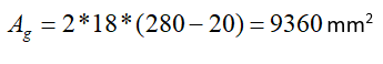
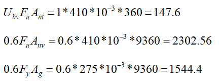
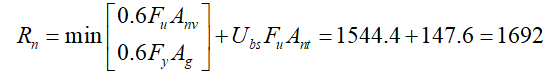
Beam Flange Block Shear
|
|
|
|
|
|
|
|
|
|
|
|
|
|
275 N/mm2 |
|
|
|
410 N/mm2 |
|
|
|
1 |
|
|
|
|
|
|
|
|
ÇYTHYEDY 13.19 |
|
|
|
|
|
Required |
Available |
Ratio |
Control |
|---|---|---|---|
|
143.884 kN |
1269 kN |
0.113 |
√ |
Flange Plate Compression Yield
|
TO |
0.65 |
|
|
L |
20 mm |
|
|
r |
4.619 mm |
|
|
KL / r |
2.81 |
|
|
|
275 N/mm2 |
|
|
|
|
|
|
|
|
ÇYTHYEDY 13.20 (KL/r<25) |
|
|
|
|
|
Required |
Available |
Ratio |
Control |
|---|---|---|---|
|
143.884 kN |
1108.8 kN |
0.130 |
√ |
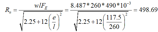
Shear Plate to Column Flange Weld Strength
|
in |
8.487 mm |
|
|
|
490 N/mm2 |
|
|
l |
260 mm |
|
|
is |
117.5 mm |
|
|
|
|
|
|
|
|
|
|
Required |
Available |
Ratio |
Control |
|---|---|---|---|
|
15.529 kN |
374.02 kN |
0.042 |
√ |
Shear Plate to Column Flange Weld Strength
|
|
490000 kN/m2 |
|
in |
The weld thickness taken from the combination menu is 0.707 * w value. 6 / 0.707 = 8.487 mm |
|
|
410 N/mm2 |
|
t |
10 mm |
|
|
|
|
|
|
|
|
|
|
|
|
|
Required |
Available |
Ratio |
Control |
|---|---|---|---|
|
66.153 kN/m |
1323 kN/m |
0.042 |
√ |
Web Plate Shear Yield
|
|
|
|
|
|
275 N/mm2 |
|
|
|
|
ÇYTHYEDY 13.17 |
|
|
|
|
|
Required |
Available |
Ratio |
Control |
|---|---|---|---|
|
15.529 kN |
429 kN |
0.036 |
√ |
Web Plate Shear Rupture
|
|
|
|
|
|
410 N/mm2 |
|
|
|
|
ÇYTHYEDY 13.18 |
|
|
|
|
|
Required |
Available |
Ratio |
Control |
|---|---|---|---|
|
15.529 kN |
376.38 kN |
0.041 |
√ |
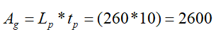
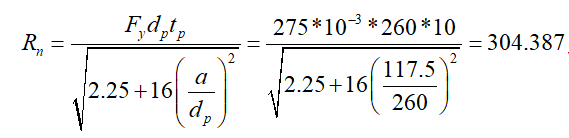
Web Plate Flexural Yield
|
|
260 mm |
|
|
|
275 N/mm2 |
|
|
|
10 mm |
|
|
|
117.5 mm |
|
|
|
|
|
|
|
|
|
|
Required |
Available |
Ratio |
Control |
|---|---|---|---|
|
15.529 kN |
273.948 kN |
0.057 |
√ |
Column Panel Zone Shear
|
|
1621.397 kN |
ÇYTHYEDY 13.29a |
|
|
|
|
|
|
275000 kN/m2 |
|
|
|
28634.759 mm2 |
|
|
|
650 mm |
|
|
|
16 mm |
|
|
|
|
|
|
|
|
|
|
Required |
Available |
Ratio |
Control |
|---|---|---|---|
|
103.141 kN |
1544.4 kN |
0.067 |
√ |
Next Topic